
Simple 50 to 300 MHz Colpitts Oscillator

The Colpitts oscillator is a widely used configuration in electronic circuits, particularly for generating high-frequency signals. This oscillator employs a combination of an inductor and two capacitors to form a resonant tank circuit, which determines the oscillation frequency. The fundamental operation of the Colpitts oscillator relies on the feedback network formed by the capacitors, which allows for stable oscillation at the desired frequency.
In this specific design, the grounded base configuration is advantageous because it minimizes the effects of parasitic capacitances and enhances frequency stability. The feedback from the collector to the emitter plays a crucial role in maintaining oscillation while ensuring that the output signal remains clean and free from distortion.
The frequency of oscillation can be calculated using the formula:
\[ f = \frac{1}{2\pi\sqrt{L \cdot C_{\text{total}}}} \]
where \(L\) is the inductance and \(C_{\text{total}}\) is the equivalent capacitance of the two capacitors in series. The tuning range of 50 MHz to 300 MHz indicates the versatility of the oscillator, allowing it to be used in various applications, such as RF transmission, signal modulation, and frequency synthesis.
The simplicity of the Colpitts oscillator circuit means that it requires a minimal number of components, making it cost-effective and easy to implement in practical applications. The choice of components, including the inductor and capacitors, should be made carefully to ensure the desired frequency range and performance characteristics are achieved. Proper layout and design considerations are essential to minimize stray capacitance and inductance, which can adversely affect the oscillator's performance.
Overall, the high-efficiency Colpitts oscillator is an excellent choice for applications requiring stable and reliable high-frequency signal generation.Simple high efficiency Colpitts oscillator. In the higher frequency ranges, above 50 MHz, Colpitts oscillators are used because stray circuit capacitance will be in parallel with desired feedback capacitance and not cause undesirable spurious resonances that might occur with the tapped coil Hartley design. The FM VCO shown is a grounded base desig n with feedback from collector to emitter. A Colpitts oscillator is one of a number of designs for electronic oscillator circuits using the combination of an inductance with a capacitor for frequency determination. As you can see in the circuit diagram, this electronic project require few electronic parts an provide a 50 MHz-300MHz VCO with a tuning range of 2:1.
link 🔗 External reference
Related Circuits
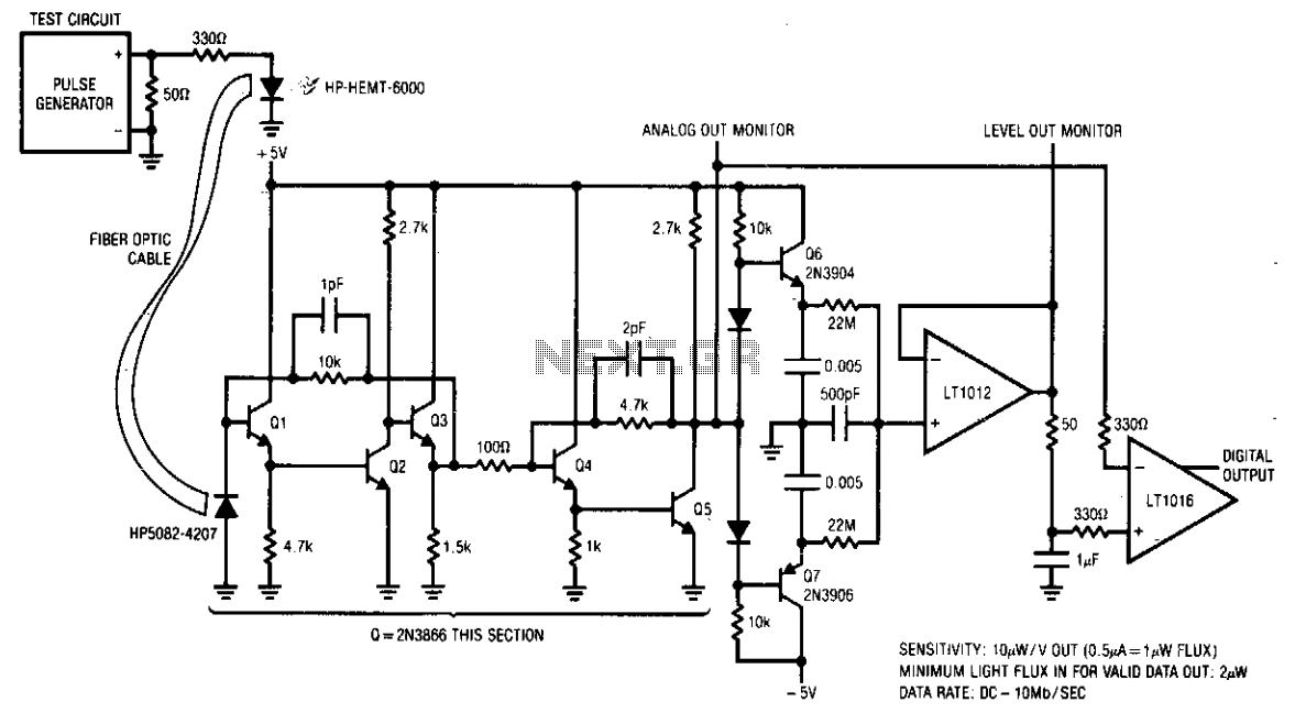
The receiver is designed to accurately condition a wide range of light inputs at data rates of up to 10 MHz. The optical signal is detected by a PIN photodiode and amplified by a broadband feedback stage comprising transistors...
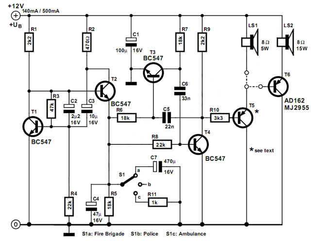
The circuit described here can generate three distinct US-style siren sounds: police, ambulance, and fire engine. The desired sound can be selected using switch S1. This circuit is suitable for various applications, including toys like model vehicles and alarm...
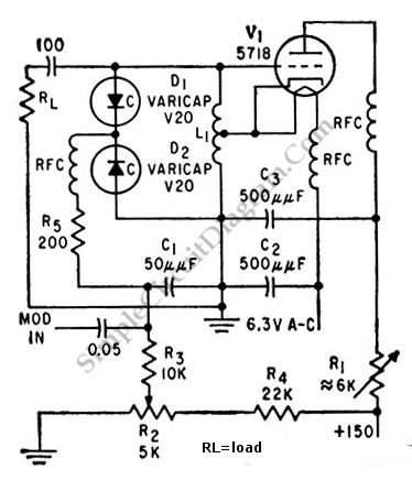
This is a 100 MHz varicap oscillator circuit. It can provide modulation signals of less than 28 V and a frequency deviation of 28 MHz peak-to-peak. The 100 MHz varicap oscillator circuit utilizes a varactor diode, which is a semiconductor...
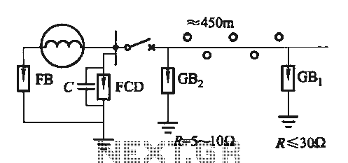
Direct distribution lightning generator with a capacity range of 300 to 1500 kW, designed for single-phase applications. The generator facilitates the direct distribution of electrical energy, providing reliable performance for various applications. The lightning generator operates within a specified power...
Many consumer electronic devices, such as televisions, VCRs, and CD/DVD players, utilize infrared remote controls. In certain situations, it is beneficial to enhance the control range. This circuit is designed to receive the infrared signal from a remote control...
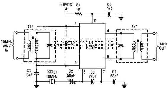
This simple frequency converter mixes the 15-MHz WWV/WVH signal with a 16-MHz signal from the local oscillator (LO) to convert it down to 1 MHz, enabling it to be received on an AM-band receiver. The frequency converter operates by utilizing...