
Simple Police Siren US-Style

The circuit operates by allowing the user to select between three siren sound profiles through a switch (S1). Each sound profile is generated by modulating the output of the circuit, which is designed to mimic the audio characteristics of police, ambulance, and fire engine sirens. The selection mechanism is straightforward, enabling quick changes in sound output based on user preference or operational requirements.
In terms of component selection, the BC337 transistor is a suitable choice for driving smaller loudspeakers in toy applications due to its efficiency and ability to handle moderate current loads. When a louder output is needed, the BD136 is introduced, which is capable of driving larger speakers without distortion. The choice of a 5W loudspeaker allows for a more pronounced sound, making it ideal for applications where sound clarity is critical.
For applications demanding even higher sound levels, the circuit design incorporates an additional stage using T6, which can handle significantly higher power loads. The use of transistors like the AD162 or MJ2955 for T6 ensures that the circuit can sustain prolonged operation without overheating, provided that adequate thermal management is employed. This feature is essential in scenarios where the siren may be activated for extended periods, such as in security systems or emergency response vehicles.
The power supply requirements vary based on the desired output volume. A 9V supply is adequate for basic operation, while a 12V supply is necessary for higher power applications. The circuit's design allows for flexibility in power supply choice, accommodating various use cases from battery-operated toys to more robust alarm systems.
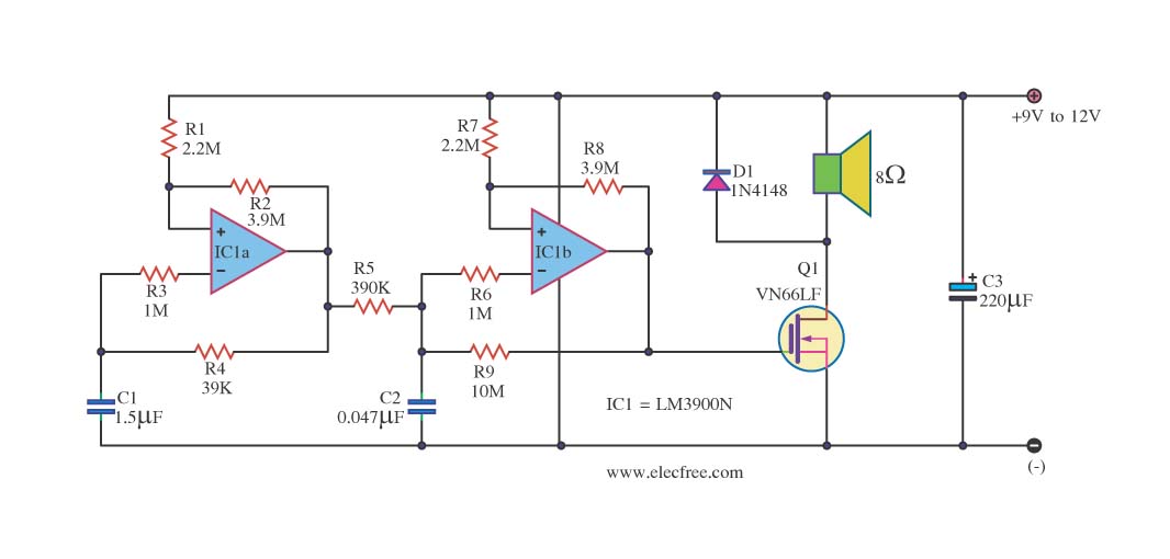
Overall, this circuit provides a versatile solution for generating realistic siren sounds, with the capability to adapt to different power and volume requirements, making it suitable for a wide range of applications in both consumer electronics and professional systems.The circuit described here can create three different US-style` siren sounds: police, ambulance and fire engine. The desired sound can be selected using switch S1. The circuit can be used in toys (such as model vehicles), as part of an alarm system, and in many other applications.
For use in a toy, a BC337 is an adequate device for driver T5, sinc e it is capable of directly driving a 200mW (8 ©) loudspeaker. In this case the current consumption from a 9 V power supply is around 140 mA. If a louder sound is required, a BD136 is recommended: this can drive a 5W (8 ©) loudspeaker. The current consumption from a 12 V supply will then be about 180mA. If still more volume is desired, then T5 (a BD136) can be used as a first driver stage, and a 15W (8 ©) loudspeaker can be connected via output transistor T6. Here an AD162 or an MJ2955 can be used, which, for continuous operation, must be provided with cooling.
The peak current consumption of the circuit will now be about 500mA with a 12V power supply. Capacitor C1 is not required for battery operation. 🔗 External reference
Related Circuits

A "Cell Jammer" is simply another term for a "Dirty Transmitter," which transmits within the cellular phone frequency bands. In reality, the more interference it generates, the more effective it is. A cell jammer operates by emitting signals that interfere...
This circuit is a sound generator designed to create a super siren alarm signal using a live frequency generator circuit that incorporates an operational amplifier (op-amp). The circuit operates on the principle that when switch S1 is not pressed,...
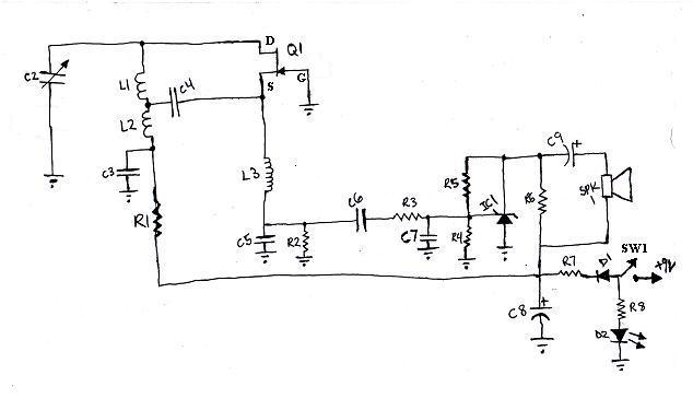
L1 and L2 were constructed by wrapping three tight loops side by side around a Sharpie marker. L2 was additionally created by wrapping approximately 8 inches of 35 AWG magnet wire around a ferrite core, ensuring that the windings...
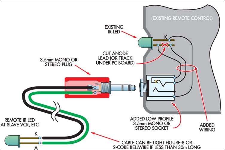
This ultra-simple remote control extender is ideal for use with a hidden video recorder. The recorder is a Panasonic NV-SD200 and is employed as part of a camera surveillance system. A PICAXE-08-based circuit detects events and controls the recorder....
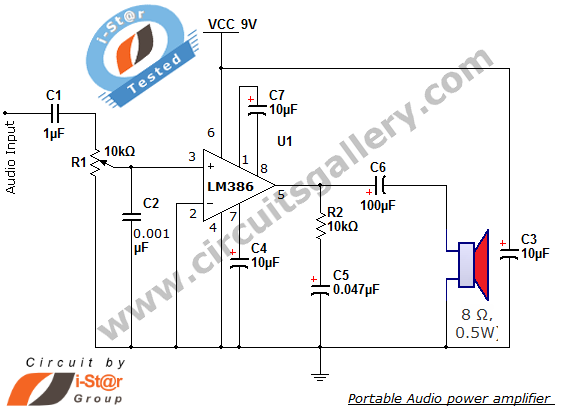
The i-St@r presents a simple mini audio amplifier circuit schematic utilizing the LM386 low voltage audio power amplifier IC. This circuit is designed to power medium-sized speakers from a music player that typically drives only earphones (LM386 headphone). The...
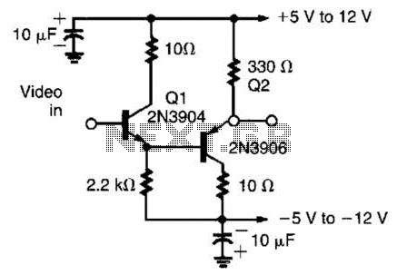
This circuit has demonstrated effectiveness as a video buffer and can easily drive a 75-ohm load to a 1.5-V peak-to-peak output. The bandwidth exceeds 20 MHz, and the DC offset is less than 0.05 V, attributed to the difference...