
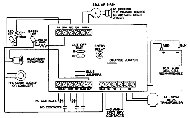
Simple 6-Input Alarm

This alarm circuit utilizes the 555 timer in a monostable configuration to provide a simple yet effective security solution for a garage or rumpus room. The 555 timer (IC1) serves as the core of the circuit, allowing for a customizable delay period that determines how long the alarm will sound. The adjustable timing is achieved through potentiometer VR1, which modifies the charge time of the timing capacitor, thus influencing the duration of the siren's activation.
The input mechanism relies on detecting negative-going signals, which are typically generated by various types of sensors. These sensors can be activated by unauthorized access or movement within the monitored area. The circuit's design allows for flexibility in choice of detection devices, making it versatile for different applications. For instance, reed switches can be placed on doors, pressure mats can be positioned on the floor, and IR detectors can be installed to monitor movement across a designated area.
When a sensor is triggered, the resulting negative pulse is coupled to pin 2 of the 555 timer through a 10 µF capacitor, ensuring that the pulse is clean and free from noise. The series diodes (D2-D7) protect the circuit by preventing back voltage from affecting sensitive components. Once triggered, the 555 timer output (pin 3) goes high, disabling relay RLY1, which in turn activates the piezo siren. The siren will sound for the duration set by VR1, alerting occupants to potential intrusions.
Relay RLY2 plays a crucial role in the alarm system by keeping the strobe light operational even after the initial trigger event. This is accomplished through a latching mechanism that maintains the relay in an energized state until the alarm is manually reset via the keyswitch. This feature enhances the visibility of the alarm condition, providing an additional layer of security.
Overall, the circuit is designed with user-friendliness in mind, allowing for easy assembly on Veroboard and straightforward integration of various sensors. The requirement that all switches must be open before the alarm is activated ensures that false alarms are minimized, making it a reliable solution for protecting spaces like garages and rumpus rooms.This simple alarm circuit was designed for use in a combined garage and rumpus room. It can be assembled on Veroboard and uses just one IC plus a handful of cheap components. The circuit is based on a straightforward 555 timer circuit (IC1). This is wired as a monostable and sets the siren period which is adjustable up to about three minutes using potentiometer VR1. In operation, IC1`s pin 2 input monitors the detector circuit for negative-going signals. When a switch is closed, a brief negative-going pulse is applied to pin 2 via a 10 µF capacitor and its corresponding series diode (D2-D7). This triggers IC1 which switches its pin 3 output high and switches off relay RLY1 (ie, RLY1 is normally on).
As a result, the piezo siren sounds for the duration of the monostable period. In addition, relay RLY2 is turned on via diode D9 and latches on via D10. This means that the strobe light (which is wired to the normally open contact) will continue to flash until the alarm is switched off (via the keyswitch). At the end of the monostable period, RLY1 turns off and this turns off the piezo siren. The circuit can then be retriggered by any further trigger inputs from the switches. A variety of detectors with normally open contacts can be used for the switches, including reed switches, pressure mats, IR detectors and glass breakage detectors.
All switches must be open before the alarm is switched on. 🔗 External reference
Related Circuits
The following alarm circuit is designed with features that may be suitable for residential and commercial alarm system applications. It has a 12V and 1.5A regulated power supply. Furthermore, this residential alarm circuit also includes a delay circuit, a...

In this fire alarm circuit project, a thermistor functions as the heat sensor. When the temperature rises, its resistance decreases, and conversely, when the temperature falls, its resistance increases. Under normal conditions... In this fire alarm circuit, the thermistor is...

Programming of the PIC microcontroller is required prior to its utilization in this circuit, which necessitates the use of a programmer. A suitable programmer can be located by searching for "Multi-PIC Programmer." The PIC microcontroller serves as the core component...

This is a small TV transmitter circuit that transmits in VHF, utilizing negative sound modulation and PAL video modulation. It is suitable for countries that use the B and G system. T1 refers to a type of transformer. The...

The simple circuit generates an audible alarm notification, functioning as a burglar alarm utilizing five transistors. This circuit operates as a basic burglar alarm system designed to emit an audible sound when triggered. The core component of the circuit is...

A simple yet reliable car battery tester circuit diagram. This circuit utilizes the popular and easily accessible LM3914 integrated circuit (IC). The LM3914 is straightforward to operate, does not require external voltage regulators due to its built-in voltage regulator,...
Warning: include(partials/cookie-banner.php): Failed to open stream: Permission denied in /var/www/html/nextgr/view-circuit.php on line 713
Warning: include(): Failed opening 'partials/cookie-banner.php' for inclusion (include_path='.:/usr/share/php') in /var/www/html/nextgr/view-circuit.php on line 713