
Simple Astable 555 Timer IC Flasher
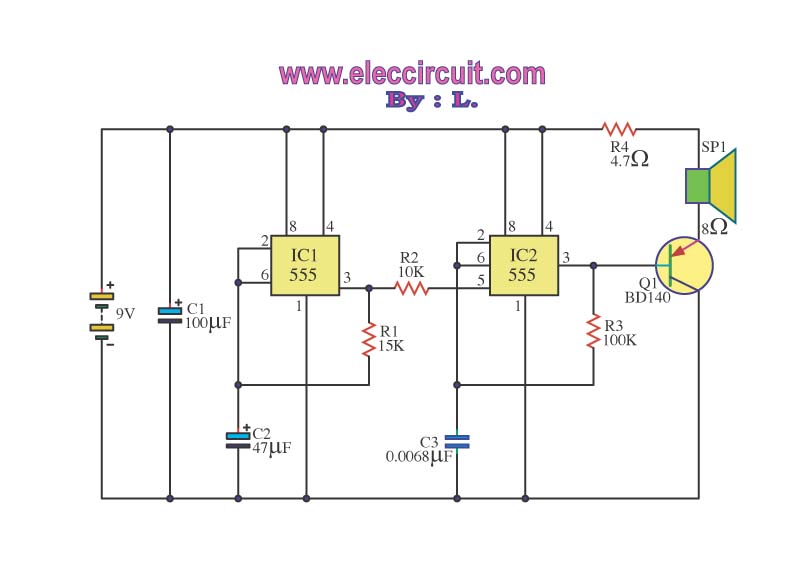
The circuit utilizes a 555 timer in astable mode, where it generates a square wave output that alternately activates two LEDs. The frequency of oscillation is primarily determined by the resistor-capacitor (RC) time constant formed by the 2.2kΩ resistor, the 47kΩ resistor, and the 10µF capacitor. The timing interval for the high and low states of the output can be calculated using the formula:
\[
f = \frac{1.44}{(R1 + 2R2) \times C}
\]
where \( R1 \) is the 2.2kΩ resistor, \( R2 \) is the 47kΩ resistor, and \( C \) is the capacitance in farads.
The output from the 555 timer is connected to the anodes of the two LEDs, with the cathodes connected to ground through appropriate current-limiting resistors. This configuration allows one LED to turn on while the other turns off, creating a flashing effect. By substituting the fixed 47kΩ resistor with a potentiometer, users can vary the resistance, thereby adjusting the flashing speed to suit their preferences.
The 10µF capacitor can also be varied to influence the timing characteristics of the circuit. Larger capacitance values will result in longer flashing intervals, while smaller values will increase the frequency of the flashing.
To enhance the visual effect of the flashing LEDs and simulate a police car light pattern, additional circuitry can be introduced. This may involve using additional 555 timers or other timing circuits to create a more complex flashing sequence. The goal is to create a pattern that alternates quickly between the two LEDs, possibly incorporating a third LED for a tri-color effect typical of emergency vehicles.
In conclusion, this simple LED flasher circuit using a 555 timer is an excellent project for beginners, offering opportunities for experimentation and modification to achieve various lighting effects.For a lower parts count than the 2 transistor multivibrators, 2 LEDs can be alternately flashed with a 555 integrated circuit configured as shown in Schematic 2. I chose the combination of a 2K2 and a 47K resistor to determine the oscillation frequency along with the 10 uF capacitor connected to pins 2 and 6.
You can practically change the (R Spee d) 47K value to between 10K and 100K or more. Greater resistance = lower speed. You may also wish to connect up a 100K or so potentiometer instead of the 47K resistor for a variable speed version. Additionally, the 10 uF capacitor value can be changed. Feel free to experiment. Although, alternately flashing LEDs is great for the beginner to electronics, the basic one ON, one OFF circuit gets boring quickly.
In the next section, we will try to improve the look and try to approximate a flash like a police car (within limits). 🔗 External reference
Related Circuits
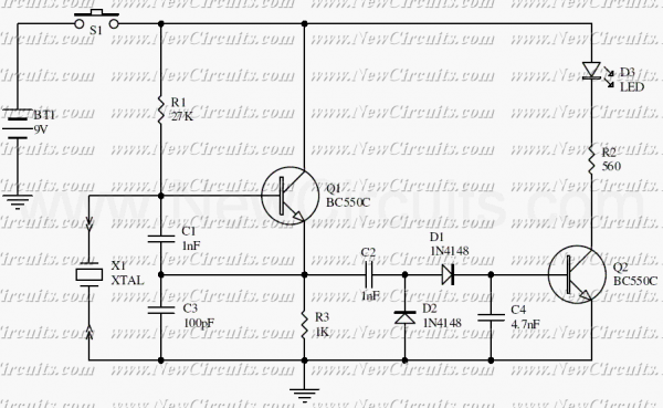
This is a simple XTal tester circuit. T1 and XTal have formed an oscillator. C1 and C2 are voltage divider for oscillator. if the XTal is safe, the oscillator will work well and its output voltage will be rectified...
The simple mixer schematic is based on the common base principle, where input voltages are transformed into alternating currents that are summed to form the output. The simple mixer circuit utilizes the common base configuration of a transistor, which is...
The circuit serves as a foundational design, requiring experimentation for specific applications. In popular microwave bands, local oscillators (LOs) are typically generated using overtone crystal oscillators followed by multipliers. A table presents the standard LO frequencies for narrowband segments,...
Wilf Rigter simplified this circuit a bit, made it phototropic, and doubled it up to yield a photopopper design in a post later the same day. I’ve got this design written up elsewhere in the library. The circuit described is...
The operation of the circuit is divided into three parts: low frequency production, high frequency manufacturing, and low frequency extension. The described circuit functions by segmenting its operation into three distinct sections, each serving a specific purpose in the overall...
The IC555 is an on-chip multivibrator that allows the design of astable, monostable, and bistable multivibrators. Its primary applications include generating timing signals, clock waveforms, synchronizing signals, and square wave oscillators, among others. This document will discuss various applications...