
working with ic555
The IC555 multivibrator can be configured in various modes to suit different applications, including timing circuits, pulse width modulation, and frequency generation. In astable mode, the IC555 continuously oscillates between high and low states, creating a square wave output. The frequency and duty cycle of this output are determined by the resistors R1, R2, and the capacitor C. The equations governing these parameters are derived from the charging and discharging cycles of the capacitor through the resistors.
In practical applications, the use of potentiometers allows for fine-tuning the frequency and duty cycle to meet specific requirements. The connection of a diode across R2, as mentioned, is a common technique to achieve a 50% duty cycle, as it alters the charging and discharging paths of the capacitor during the oscillation cycle.
For monostable applications, the IC555 can generate a single output pulse in response to a triggering event. The duration of this pulse is determined by the resistor and capacitor values, which can be calculated similarly to the astable configuration. The ability to generate precise timing pulses makes the IC555 a versatile component in various electronic projects, from simple timers to complex control systems.
In summary, the IC555 multivibrator is a highly adaptable device that can be configured for multiple timing and waveform generation applications. Its ease of use and flexibility in design make it a staple in electronics, suitable for both beginners and experienced engineers alike.As we know its on chip multivibrator means with IC555 one can design astable, monostable, bistable multivibrators. Its main applications are to generate timings, clock waveform, generate synchronizing signals, square wave oscillator and many more.
So here we are going to discuss some of the applications of IC555. But before that I will start with the basic theory. Here I shall not discuss the internal block diagram and theory of IC555 that how does it work in astable or monostable operation as everybody is already familiar with that. But here there is a practical approach given to explain how to design different applications of the chip.
Here frequency and duty cycle are the design parameters and we have to find out three unknowns R1, R2 & C. For given values of design parameters, we have to find out these three unknown. Here we have to assume the value of C, as from two equation we can not find three unknown. Let us assume C=0. 01 microF. Substituting this value into first equation From the equations (3) and (4) we can find out R1 = 720 ohm and R2 = 1.
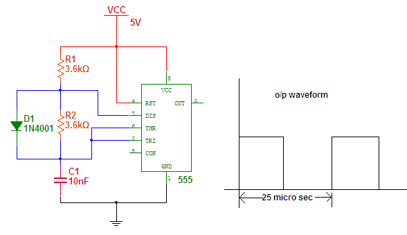
44K. The nearest practical values will be 715 ohm and 1. 43K. Substituting these values back into the design equations, we shall get freq = 40 KHz (nearly equal to) and duty cycle = 60%. If we use potentiometer of 4. 7K instead of fixed value of R2 then we can set the exact 40 KHz freq. by tuning value of R2. Now it is not possible to design an astable multivibrator with exact 50% duty cycle using these equations and above circuit.
If you want to design an astable multivibrator for exact 50% duty cycle then we have to do slight modification in above circuit by connecting one diode across resistor R2. Here by assuming value of capacitor one can easily find the value of resistor. Duty cycle will be always 50%. For above values of frequency (40 KHz) and capacitor (10 nF) the value of R will be 3. 6K. The circuit is as shown below. If we take nearest value of 1K then time period will be 1. 1ms. Here also instead of using any fix value of resistance if we use potentiometer of 10K then we can get variable time pulse (1 - 11 ms) in the output.
The circuit is as shown. this is the easiest application of IC555 because there is no any design equation. just we have to apply high / low logic on pins 6 / 2 to get low / high output. here is the circuit. As shown in circuit pin no 6 is connected with ground through R1 and pin no 2 is connected with Vcc through R2. Two push button switches S1 - S2 are connected as shown to apply high - low inputs to these pins. the operation is very simple. When S1 is pressed momentarily the output goes high and when S2 is pressed the output goes low. 🔗 External reference
Related Circuits

After dismantling a Chinese copy of a Segway, an examination of the motor controller was conducted. After several hours of work with a multimeter, pen, paper, and KiCad, a block diagram and schematic of the motor controller were developed....
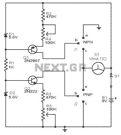
This circuit is a simple device for testing the hfe (current gain) of both PNP and NPN transistors, with the capability to measure hfe values as high as 1000. It operates using two constant current sources formed by transistors...
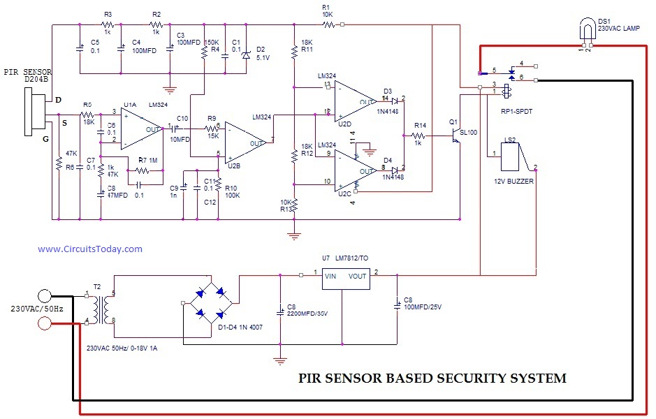
PIR (Passive Infrared Radial) Sensor-Based Security System, circuit diagram, working, applications. The PIR (Passive Infrared) sensor-based security system is designed to detect motion by measuring changes in infrared radiation emitted by objects in its vicinity, particularly warm bodies such as...
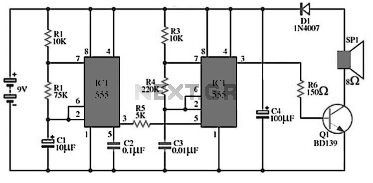
The circuit utilizes IC1 to create an astable multivibrator configuration. It is designed to generate a low-frequency output of approximately 1 Hz at pin 3, which is determined by the resistor values R1, R2 and capacitor C1. The output...
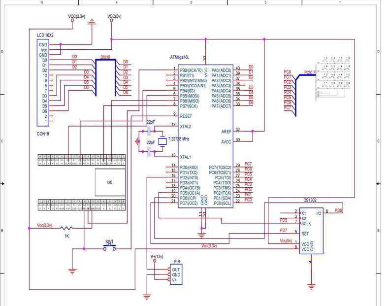
TCP based security system using the Ethernet module offered within the contest, an ATmega16L microcontroller, a PIR as a sensor and few other peripheral devices, which is specially targeted for homes and small business owners. I have used through...
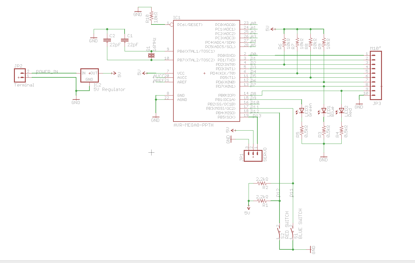
A circuit utilizes a keypad, a servo, and several LEDs, connected to an Arduino Uno. The objective was to integrate all components onto a single PCB, effectively creating a custom version of the Arduino. Upon startup, the red LED...
Warning: include(partials/cookie-banner.php): Failed to open stream: Permission denied in /var/www/html/nextgr/view-circuit.php on line 713
Warning: include(): Failed opening 'partials/cookie-banner.php' for inclusion (include_path='.:/usr/share/php') in /var/www/html/nextgr/view-circuit.php on line 713