
Simple Short-Circuit Detection
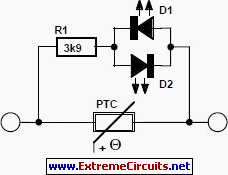
This circuit effectively addresses the challenge of over-current protection in model train layouts by utilizing multifuses that automatically reset after a fault is cleared. The design allows for easy identification of the affected section through the use of LED indicators, which enhances the user experience by minimizing downtime during troubleshooting. The choice of low-current LEDs ensures that the circuit remains efficient, while the adjustable resistor allows for customization based on user preferences for brightness. The dual LED configuration accommodates the bidirectional nature of train operations, ensuring that the circuit functions correctly regardless of the current direction. By selecting an appropriate multifuse with a trip current slightly above the maximum locomotive current, the circuit provides reliable protection without unnecessary interruptions to the operation of the model railway. This design exemplifies a practical solution for hobbyists seeking to enhance their model train systems with effective over-current protection mechanisms.This circuit is suitable in every situation where over-current protection is required. Here we give an example from the model train world. Every seasoned model train enthusiast knows that there is nothing worse than having to find the cause of a short-circuit. On a small model railway with one locomotive it is obviously fairly easy, but on large l ayouts all locomotives stand still when there is a short and then you have to check each one in turn to find the culprit. If the track is divided into sections then we can use this super simple circuit to make our lives a lot easier.
A multifuse is inserted into one of the supply lines for each of the sections. (A multifuse is also called a multiswitch, polyfuse or polyswitch, depending on the manufacturer). This is a type of fuse that cools down and conducts normally again once the short has been removed. The advantage is that only the section with the short becomes isolated. All the other locomotives in the other sections continue to move. The stationary locomotive is in principle the culprit, but it`s quite likely that several locomotives aren`t moving since not all of them would be travelling in the first place. For this reason we connect an LED indicator across each multifuse, making it clear which section caused the problem.
You can choose any color LED, but we recommend that you use low-current types that emit a lot of light at only a few mA. The value of the current limiting resistor may be changed to give an acceptable LED brightness. As long as the current is small, the resistance of the multifuse is also low and there will barely be a voltage drop.
At high currents the resistance increases, which causes a voltage drop across the multi-fuse that is large enough to light up the LED. As we don`t know the direction of the current flow (the train could be moving either forwards or backwards and digital controls use an alternating current) we connected two LEDs in parallel with opposite polarities.
Multi-fuses are available for many different trip currents. Choose a value that is slightly higher than the maximum current consumption of a locomotive in a section. The table below shows the characteristics of several types from the MF-R series made by Bourns. (Raychem is another well-known manufacturer of poly-switches. ) Ihold is the current at which the multifuse still conducts normally, Itrip is the short-circuit current.
🔗 External reference
Related Circuits
This two-transistor white noise generator exhibits approximately 30 dB more noise than traditional designs. Transistors Q1 and Q2 can be any small-signal transistors with a beta rating of up to 400. The reverse-biased emitter-base junction of Q1 serves as...
This temperature controller utilizes an LM135/235/335 temperature sensor and is designed to maintain a small environment at a warm or hot temperature. A schematic diagram is provided. The temperature controller circuit is centered around the LM135/235/335 series of temperature sensors,...
The differential input stage utilizes the integrated differential transistors 2SC1583 and 2SA798, with the amplified signal directed to the power amplifier tubes VT5 and VT6. The performance of the charge directly influences the overall performance of the power amplifier...
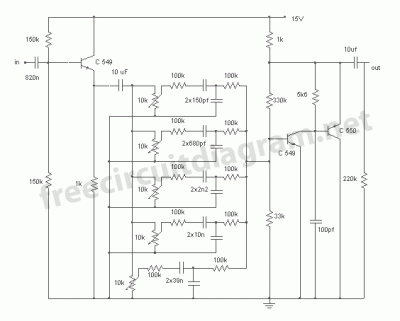
This circuit is a five-channel equalizer designed for a single line channel. The working principle of this series involves a series of frequency filters with a center frequency of 10 Hz. The five-channel equalizer circuit is structured to manipulate audio...
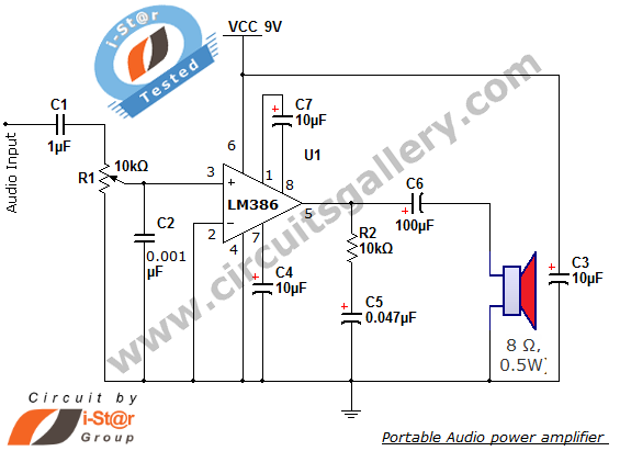
The i-St@r presents a simple mini audio amplifier circuit schematic utilizing the LM386 low voltage audio power amplifier IC. This circuit is designed to power medium-sized speakers from a music player that typically drives only earphones (LM386 headphone). The...
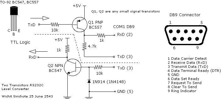
There are many who built the Easy Programmer or C-52 Evaluation Board, asking for the RS232C level converter chip, DS275. Many have changed to MAX232 instead, because it is not available in their home. Here is another simple and...