
Simple Buzzer driver with 555
The circuit utilizes the popular 555 timer IC configured in an astable mode, which allows it to continuously oscillate between high and low output states without any external triggering. In this configuration, the 555 timer generates a square wave output, which can be used to drive a speaker or buzzer, producing an audible tone.
The timing components for the 555 timer in astable mode include two resistors (R1 and R2) and a capacitor (C1). In this case, one of the resistors is specified as 10KΩ, which can be adjusted to modify the frequency of oscillation. The second resistor's value can also be selected based on the desired frequency. The capacitor value will also influence the frequency; a typical choice might be in the range of microfarads (μF), depending on the desired output characteristics.
The frequency (f) of the output square wave can be calculated using the formula:
\[
f = \frac{1.44}{(R1 + 2R2) \cdot C1}
\]
Where R1 is the resistor connected from pin 7 (discharge) to Vcc, R2 is the resistor from pin 7 to pin 6 (threshold), and C1 is the capacitor from pin 6 to ground. The output frequency can be adjusted by changing the values of R1, R2, or C1, allowing for flexibility in sound generation.
When the circuit is powered, the 555 timer oscillates, causing the output pin (pin 3) to switch between high and low states, which drives the connected speaker or buzzer. The resulting sound is a shrill tone, which can be altered in pitch by varying the resistance and capacitance values. This simple circuit can be employed in various applications, such as alarms, sound effects in toys, or as a basic tone generator for educational purposes.This very simple circuit just uses a couple of resistors, a capacitor and the easily available 555 timer IC. The 555 is setup as an astable multivibrator operating at a frequency of about 1kHz that produces a shrill noise when switched on.
The frequency can be changed by varying the 10K resistor. 🔗 External reference
Related Circuits

The circuit described here was designed as an addition to a remotely controlled garage door opener. The problem was that a brief burst of interference, arising from a thunderstorm or a mains spike, was enough to trigger the mechanism,...
This simple water detector circuit utilizes alternating voltage to prevent electrode corrosion. It is easy to construct and employs N1 as a trigger Schmitt gate to generate the AC signal. When a conductive substance, such as an aqueous solution,...
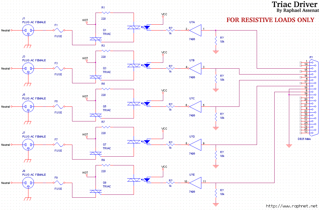
Controlling room lighting using a computer. Triacs and opto-couplers have been purchased for this purpose. A schematic was drawn and a prototype was built, which functioned correctly. Although not visible in the pictures, there is a cable extending from...
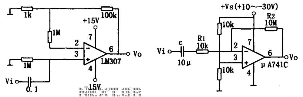
The simple audio amplifier circuit is illustrated in the figure. Utilizing an integrated op-amp configuration, this audio amplifier is stable and allows for easy negative feedback, facilitating the achievement of equalization characteristics. Additionally, the crosstalk between channels is minimal,...

The ADM3251E is a transceiver that features high-speed operation, 2.5 kV full isolation, and a single channel for RS-232/V.28 communication. This device operates from a single 5 V power supply. The ADM3251E transceiver is designed for robust communication in environments...
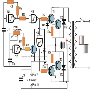
The PWM-controlled modified sine wave inverter circuit presented here utilizes a single 4093 integrated circuit (IC) for its specified functions. This IC consists of four NAND gates, with two configured as oscillators and the other two serving as buffers....