
Simple CB receiver with SO42P
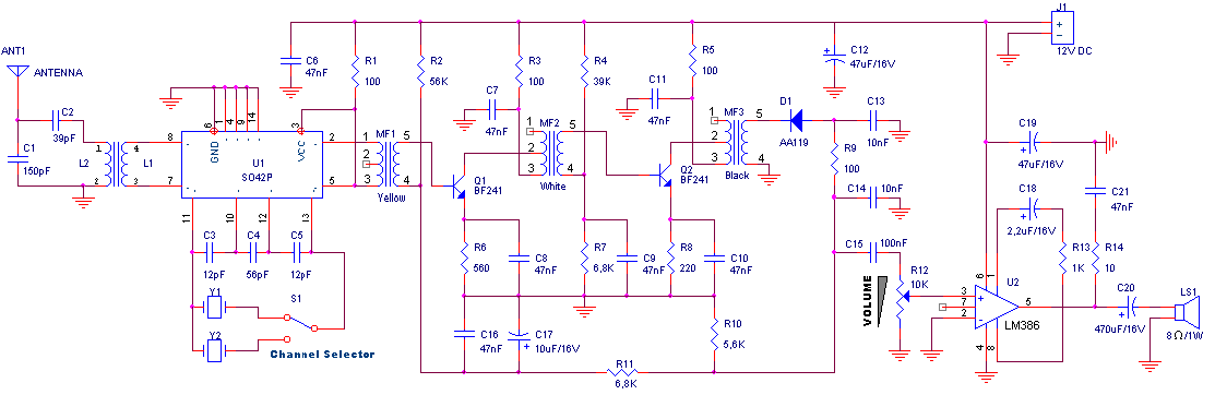
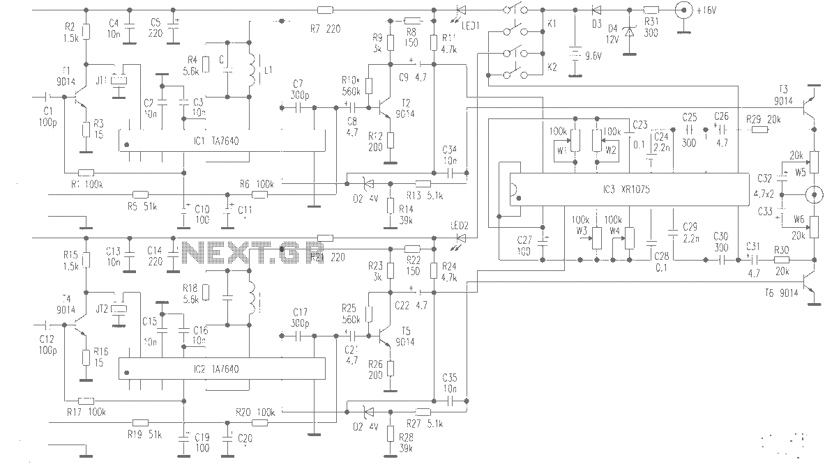
The circuit described is for a CB (Citizens Band) radio transmitter and receiver setup operating at a frequency of approximately 27 MHz. The primary components include a transmitter or generator, a receiver, a loudspeaker, and an inductor (L1/L2). The setup requires a 12V power supply for the receiver, which is essential for its operation. The regulation of sound is achieved through a potentiometer (R12) that allows for volume adjustment.
To set up the system, a piece of approximately one meter of cable is used as an antenna. Once the antenna is connected, the transmitter or generator is powered on, and the user is advised to emit signals from a distance of about 10 meters from the receiver. The receiver should be tuned to the same channel as the transmitter to ensure proper communication.
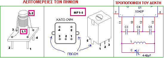
If the initial signal strength is insufficient, the core of the inductor (L1/L2) can be adjusted to increase the intensity of the received signal. The user can then explore different medium frequencies, starting from a specified frequency (MF3), to find the optimal setting for the strongest signal reception.
In cases where specific components, such as crystals (referred to as "krysta'lloys"), are unavailable, it is possible to modify the circuit. Instead of using a crystal, LC circuits can be employed, each tuned to a different channel, allowing for flexibility in the design. The receiver can be designed to work in conjunction with the CB transmitter, forming a complete CB station capable of two-way communication. This configuration is suitable for amateur radio enthusiasts and can be tailored to specific needs based on available components and desired functionality.For the regulation needs a transmitter or generator in mpa'nta the CB, that is to say in the region 27MHz. If you have a certain friend with CB, you convince you to help. Connect a piece of cable around in the one metre in the place of aerial. Be supplied the receptor with + 12V and turn in half the potentiometer of regulation of sound (R12). Turn on the generator or the transmitter CB and you emit in distance of 10 metres roughly from the receptor, in the channel that receives the receptor.
From the loudspeaker it will be supposed it begins to be heard what you emit and if it does not have big force, you turn the core of inductor L1/L2 until you have a increase of intensity. After this you can continue with the various medium frequencies beginning from black (MF3) until you have the biggest intensity.
If it is heard mjkrofwnjsmo's, you lower little the intensity of loudspeaker or you remove the transmitter from the receptor. If you cannot find krysta'lloys you can make the modification that shows the form. That is to say, instead of crystal you in joint action put respectively coordinated circuits with LC each one in different channel. The receptor this can combine itself with the transmitter CB in order to you manufacture a complete station CB.
🔗 External reference
Related Circuits
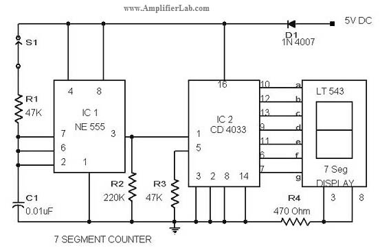
The circuit diagram of a 7-segment counter circuit has been published here. This circuit consists of the counter IC CD4033 as its central component. The 7-segment counter circuit utilizing the CD4033 integrated circuit (IC) is designed to display decimal digits...
The simple mixer schematic is based on the common base principle, where input voltages are transformed into alternating currents that are summed to form the output. The simple mixer circuit utilizes the common base configuration of a transistor, which is...
Sensitivity and selectivity are important factors for a shortwave listener considering the purchase of a new receiver. While commercially available communications equipment can meet expectations, such products tend to be expensive. Low-cost alternatives often involve homebrewed radios, with the...
The diagram illustrates a simple and efficient receiver designed for activating garage doors, starter motors, alarms, warning systems, and various other applications. The SCR utilized in this circuit features an extremely low trigger current of 30 µA, requiring only...
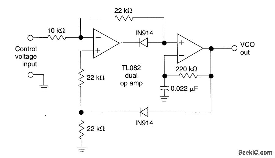
This circuit utilizes a dual operational amplifier (TL082) to create a voltage-controlled oscillator (VCO). The specified component values allow the output frequency to range from 100 Hz to 10 kHz when the input control voltage varies between 0.05 V...
The production of high-quality wireless microphones is a common aspiration among enthusiasts, but achieving a high-performance receiver is challenging. This project explores the use of salvaged FM radio cassette players to enhance an XR1075 audio processor, leading to the...