
Simple color organ
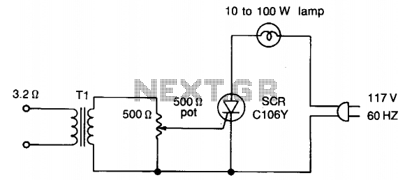
The described circuit utilizes a transformer, referred to as Tl, which serves as a matching device for various transistor types with impedance ratings ranging from 500/500 ohms to 2500/2500 ohms. This flexibility allows for compatibility with a range of audio amplifiers and ensures optimal performance based on the specific requirements of the application.
In the circuit, it is crucial to note that no connections from the silicon-controlled rectifier (SCR) or any associated components are connected to ground. This design choice enhances safety by preventing any potential ground loops that could introduce noise or create hazardous conditions. The circuit operates with a 117-V line voltage, which is standard in many regions, ensuring that the amplifier functions correctly without exceeding voltage ratings.
To facilitate user adjustments, a potentiometer, designated as Rl, is included in the design. Initially, this potentiometer should be set to the "off" position. Following this, the amplifier's volume control can be adjusted to achieve a comfortable listening level. This step is essential to establish a baseline before fine-tuning the system.
After achieving the desired volume level, the next step involves adjusting the potentiometer Rl. The goal of this adjustment is to synchronize the operation of a connected lamp with the audio signal, specifically to make the lamp throb in rhythm with the beat of the music. This visual feedback can enhance the listening experience, providing an engaging multimedia effect that responds to the audio output. Care should be taken during this adjustment to ensure that the lamp's response is not overly sensitive, which could lead to flickering or an unstable visual effect.
Overall, this circuit design emphasizes safety, flexibility, and user engagement, making it suitable for various audio applications where visual feedback is desired.Transformer Tl can be any matching transistor type in the range of 500/500 to 2500/2500 ohms. No connections from the SCR or its components are connected to ground. For safety's sake, keep the 117-V line voltage from the amplifier connections— that is the reason for using Tl. To adjust, set potentiometer Rl "off" and adjust the amplifier volume control for a normal listening level.
Then adjust the potentiometer until the lamp starts to throb in step with the beat. 🔗 External reference
Related Circuits
This is a simple microphone preamplifier circuit which you can use between your microphone and stereo amplifier. This circuit amplifier microphone suitable for use with normal home stereo amplifier line/CD/aux/tape inputs. This mic preamp can take both dynamic and...
This amplifier is designed for outdoor installation and is connected to an indoor power line box. It utilizes either 50-ohm or 75-ohm coaxial cables for the connection between indoor and outdoor units. The amplifier circuit board is depicted in...
The main part of this circuit is the LM386 amplifier chip. It also uses a transistor input to buffer the input signal and provide extra gain for the LM386. The little unit has helped me out on numerous occasions...
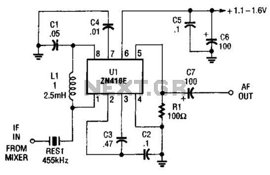
The ZN416E can be configured as a simple 455-kHz IF amplifier. In this case, the circuit's center frequency and bandwidth are set by RES1, which is a Murata CSB455E ceramic resonator. The ZN416E is a versatile integrated circuit designed specifically...
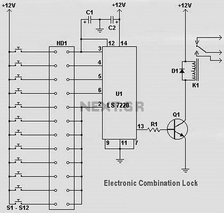
The following diagram illustrates a straightforward electronic combination lock utilizing the IC LS7220. The component part list includes: C1 = 1µF 25V, C2 = 220µF 25V, R1 = 2.2K Ohm, Q1 = 2N3904 or 2N2222, D1 = 1N4148 or...
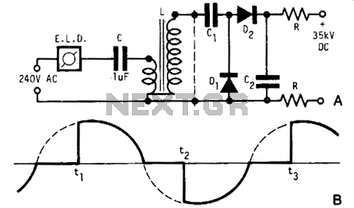
A light dimmer, a 1 µF capacitor, and a 12 V car ignition coil form a simple line-powered high-voltage generator. The current in the dimmer is illustrated in Fig. B. During the time intervals tp to t2, determined by...