
Simple high-volt supply
The circuit operates by utilizing the properties of a light dimmer, which effectively modulates the amount of power delivered to the load. The dimmer's internal triac acts as a switch that controls the timing of current flow to the capacitor and subsequently to the ignition coil. When the triac is triggered, it allows a pulse of current to flow through the primary winding of the ignition coil, inducing a magnetic field. The rapid change in current creates a high-voltage pulse in the secondary winding due to the principles of electromagnetic induction.
The capacitor, rated at 1 µF, serves as a charge storage element, accumulating energy during the brief periods when the triac is conducting. This energy is then released as a high-voltage pulse at the secondary of the coil. The frequency of operation, which is linked to the AC line frequency, contributes to the generation of high-voltage pulses at a rate consistent with the line frequency.
To convert the high-voltage alternating current (AC) output from the ignition coil into a usable high-voltage direct current (DC), a voltage doubler circuit is implemented. This circuit typically consists of two diodes (D1 and D2) and two capacitors. The selenium rectifiers are chosen for their reliability and efficiency in rectifying the high-voltage output, which is essential for applications such as powering television sets.
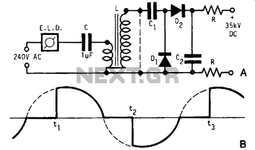
In addition to the rectification process, the inclusion of high-value output shock protection resistors is critical for safeguarding against potential high-voltage shocks. These resistors limit the current that can flow through the circuit during fault conditions, enhancing the overall safety of the high-voltage generator setup. Proper selection of resistor values and ratings is essential to ensure effective protection while maintaining the desired performance of the high-voltage output.A light dimmer, a 1 µf capacitor and a 12 V car ignition coil form the simple line powered HV generator. The current in the dimmer is shown in Fig. B. At times tp t2, set by the dimmer switch, the inner triac of the dimmer switches on, and a very high and very fast current pulse charges the capacitor through the primary of the induction coil.
Then at a rate of 120 times per second for a 60 Hz line, a very high voltage pulse appears at the secondary of the coil. To obtain an HV dc output, use a voltage doubler. Dl and D2 are selenium rectifiers (TV 18 Siemens or ITT) used for the supply of television sets. High value output shock protection resistors, R, are recommended when suitable. 🔗 External reference
Related Circuits

A simple lab power supply electronic project can be designed using this circuit diagram, which is based on the LM2576 monolithic integrated regulator that provides all the active functions for a step-down (buck) switching regulator. As seen in the...
A sawtooth wave generator circuit using a 555 IC is presented in the article below. The frequency equation is provided with the supply voltage Vcc. The sawtooth wave generator circuit utilizing a 555 timer integrated circuit (IC) is a fundamental...
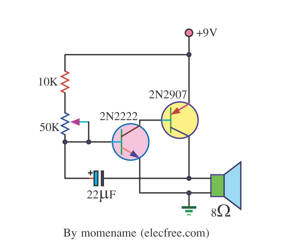
This is a simple tone oscillator generator. It uses the transistors 2N2222 and 2N2907 as the main components. The tone sound is controlled with a 50K ohm resistor (R2) and an 8-ohm speaker is utilized. The tone oscillator generator circuit...
A Variable DC Power Supply is one of the most useful tools on the electronics hobbyist's workbench. This circuit is not an absolute novelty, but it's simple, reliable, rugged, and short-proof, featuring variable voltage up to 24V and variable...
The RF stage of the receiver utilizes a transistor VT1, functioning as both a mixer and a local oscillator while also serving as a synchronous detector. A headphone cable acts as an antenna, capturing signals that are directed to...
Simple Burglar Alarm / Door Alarm Circuit Diagram. This project can be utilized to secure a door or window. It emits a loud beep and activates the room light when an intruder attempts to break the door lock. The Simple...
Warning: include(partials/cookie-banner.php): Failed to open stream: Permission denied in /var/www/html/nextgr/view-circuit.php on line 713
Warning: include(): Failed opening 'partials/cookie-banner.php' for inclusion (include_path='.:/usr/share/php') in /var/www/html/nextgr/view-circuit.php on line 713