
Simple combination lock
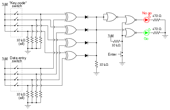
The circuit described utilizes an 8-position DIP switch for input, with two potential configurations: a single switch for both data entry and key code or two separate switch assemblies for enhanced security. The XOR gates serve as the core component for comparing the binary inputs, providing a straightforward mechanism for determining code validity. Each XOR gate compares corresponding bits from the two 4-bit binary numbers, generating a "high" output when the bits differ. This output is monitored by a diode network, which aggregates the signals and feeds them into a NOR gate.
The NOR gate's function is critical, as it ensures that the LEDs only activate when the "Enter" button is pressed. This design prevents accidental triggering of the indicators and ensures intentional user action is required for code validation. The circuit's simplicity, with only sixteen possible combinations, makes it suitable for educational purposes, illustrating fundamental concepts of logic gates and binary comparison. However, in practical implementations, additional security measures would be necessary, such as integrating alarm systems or time delays to prevent brute-force attacks on the code. The design emphasizes the importance of securely concealing the key code and provides a foundational understanding of XOR gate operations in digital logic systems.This experiment may be built using only one 8-position DIP switch, but the concept is easier to understand if two switch assemblies are used. The idea is, one switch acts to hold the correct code for unlocking the lock, while the other switch serves as a data entry point for the person trying to open the lock.
In real life, of course, the switch a ssembly with the "key" code set on it must be hidden from the sight of the person opening the lock, which means it must be physically located elsewhere from where the data entry switch assembly is. This requires two switch assemblies. However, if you understand this concept clearly, you may build a working circuit with only one 8-position switch, using the left four switches for data entry and the right four switches to hold the "key" code.
This circuit illustrates the use of XOR (Exclusive-OR) gates as bit comparators. Four of these XOR gates compare the respective bits of two 4-bit binary numbers, each number "entered" into the circuit via a set of switches. If the two numbers match, bit for bit, the green "Go" LED will light up when the "Enter" pushbutton switch is pressed.
If the two numbers do not exactly match, the red "No go" LED will light up when the "Enter" pushbutton is pressed. Because four bits provides a mere sixteen possible combinations, this lock circuit is not very sophisticated.
If it were used in a real application such as a home security system, the "No go" output would have to be connected to some kind of siren or other alarming device, so that the entry of an incorrect code would deter an unauthorized person from attempting another code entry. Otherwise, it would not take much time to try all combinations (0000 through 1111) until the correct one was found!
In this experiment, I do not describe how to work this circuit into a real security system or lock mechanism, but only how to make it recognize a pre-entered code. The "key" code that must be matched at the data entry switch array should be hidden from view, of course.
If this were part of a real security system, the data entry switch assembly would be located outside the door, and the key code switch assembly behind the door with the rest of the circuitry. In this experiment, you will likely locate the two switch assemblies on two different breadboards, but it is entirely possible to build the circuit using just a single (8-position) DIP switch assembly.
Again, the purpose of the experiment is not to make a real security system, but merely to introduce you to the principle of XOR gate code comparison. It is the nature of an XOR gate to output a "high" (1) signal if the input signals are not the same logic state.
The four XOR gates` output terminals are connected through a diode network which functions as a four-input OR gate: if any of the four XOR gates outputs a "high" signal - indicating that the entered code and the key code are not identical - then a "high" signal will be passed on to the NOR gate logic. If the two 4-bit codes are identical, then none of the XOR gate outputs will be "high, " and the pull-down resistor connected to the common sides of the diodes will provide a "low" signal state to the NOR logic.
The NOR gate logic performs a simple task: prevent either of the LEDs from turning on if the "Enter" pushbutton is not pressed. Only when this pushbutton is pressed can either of the LEDs energize. If the Enter switch is pressed and the XOR outputs are all "low, " the "Go" LED will light up, indicating that the correct code has been entered.
If the Enter switch is pressed and any of the XOR outputs are "high, " the "No go" LED will light up, indicating that an incorrect code has been entered. Again, if this were a real security system, it would be wise to have the "No go" output do something that deters an unauthorized person from discovering the correct code by trial-and-error.
In other words, there should be some sort of penalty f 🔗 External reference
Related Circuits
This clock timer uses a PIC16F628 microcontroller to display 3 and 1/2 digit time and control an external load. The clock includes a calendar with leap year and optional daylight savings adjustments. The timer output can be set from...
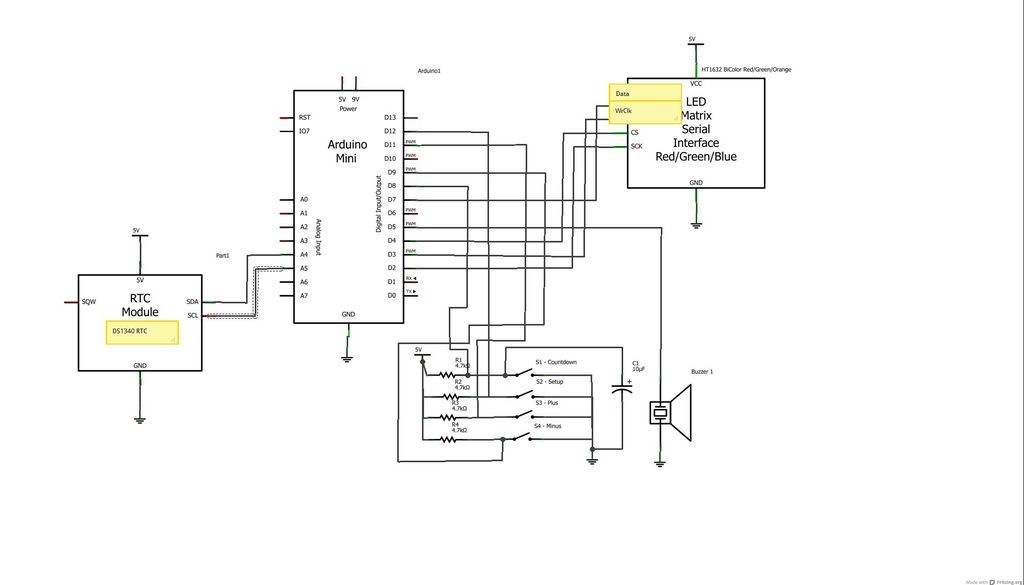
The device is designed to promote respectful time management during meetings, particularly useful in ship-room or SCRUM meetings. The following is a list of components required, including links for purchasing specific parts. It is advisable to check eBay or...
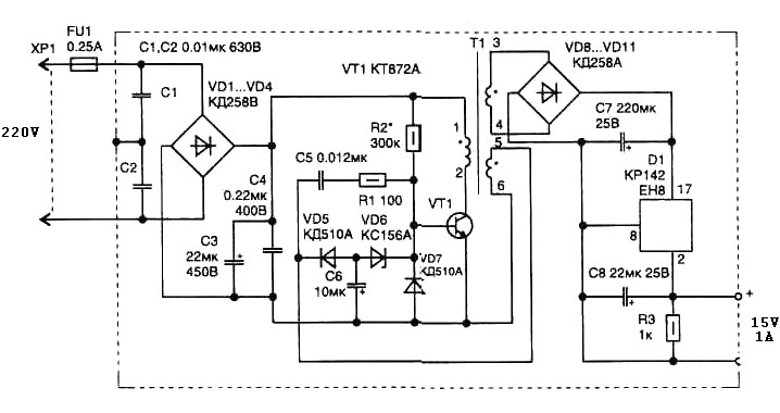
The pulse transformer T1 utilizes a ferrite core, specifically M2500NMS-2 or M2000NM9, with dimensions of Sh5h5 (cross-section of the magnetic coils at 5G—5 mm with a center gap). The winding wire is of type PEL-2. The primary winding consists...
This design was developed to create a highly stable reference locked to a 10MHz source. With minor hardware modifications and entirely new firmware, an excellent GPS Disciplined Oscillator (GPSDO) was achieved using the same circuit board. The design effectively...
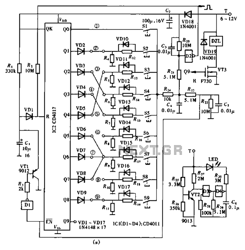
The lock circuit utilizes a decimal counter CD4017, which consists of ten output terminals. These terminals are connected through a combination that corresponds to a group of passwords, allowing for a maximum of up to 100 million combinations, hence...
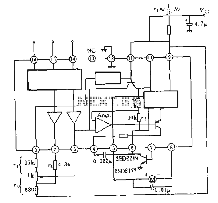
The AN6657 is a 16-pin dual in-line plastic package, while the AN6657S features a 16-pin dual flat plastic package. The speed control function operates with an internal H-bridge driver chip circuit, utilizing pins 5 and 8 for H-bridge driver...