
Simple GPS Disciplined Reference
The design of the GPS Disciplined Oscillator (GPSDO) emphasizes precision and reliability, targeting applications that require high-frequency stability and accuracy. The core component, the OCXO, is pivotal in maintaining the reference frequency, which is crucial for synchronization in telecommunications, navigation systems, and scientific instrumentation. The choice of a double-sided PCB with an extensive ground plane not only enhances electrical performance by reducing noise but also improves thermal management, which is vital for the stable operation of the OCXO.
The telemetry system integrated into the design allows for real-time monitoring of the oscillator's performance, providing insights into its stability and drift characteristics. The ability to log performance data enables users to conduct detailed analyses, ensuring that the oscillator meets the stringent requirements of high-precision applications.
Moreover, the independent real-time clock reinforces the system's robustness, allowing it to maintain accurate timekeeping even during GPS outages, which is a common scenario in various operational environments. The flexibility of the output options, including the CMOS 1pps and 10MHz outputs, provides versatility, making the GPSDO suitable for a wide range of applications, from laboratory settings to field deployments.
Overall, the design represents a sophisticated solution for achieving high-frequency stability and precision, leveraging advanced components and thoughtful engineering to meet the demands of modern electronic systems.This design came about as a result of efforts to design a high stability reference which locked to a 10MHz source. With some minor hardware adaptation and completely new firmware, it proved possible to design an excellent GPS Disciplined Oscillator (GPSDO) using the same circuit board.
The design gently locks a high performance 10MHz OCXO to the G PS or other 1pps reference, and is capable of providing an accurate reference, with high stability at the level of a few parts in 1012. The unit operates without requiring any intervention or control. A serial link provides telemetry and a user-set real-time clock. Controls are provided for initial calibration. The OCXO sine wave output can drive 50 Ohm loads (1V p-p). There is also an optional regenerated CMOS 1pps output which can be used to operate other devices, and it would be easy to swap this for a CMOS 10MHz output instead.
The clock and reference continue to operate when GPS is lost, and although the reference frequency will then very slowly change due to OCXO ageing, it is held digitally at the current operating point until GPS returns. The clock will be accurate to parts of a second per year (provided power is not lost), even if GPS is occasionally or frequently lost.
The unit is not difficult to build, although performance will be best if a double-sided PCB with extensive ground plane is used. There are six ICs and one transistor. One of the ICs in the photo above is not used. The prototype used surface mount components extensively, mostly to save space. There are no components on the back of the board except the LEDs, which are fitted when the unit is placed in the box.
The circuit board shown above was designed to fit into the lid of a standard Hammond 1590WP1 diecast box on 10mm spacers. The high stability performance is achieved through the use of a high quality SC-cut Oven Controlled Crystal Oscillator (OCXO).
This is the most expensive component in the unit, and must be of the 12V operated type with an ~8V reference output, since this temperature controlled low noise reference is used to operate the voltage control circuitry. The RAKON CFPODO family is ideal. Other manufacturers (Vectron, TEMEX, Morion, Trimble, NDK etc) make similar products. Suitable devices can often be found on internet auction sites for US$30 or so. Use the best oscillator you can afford. The serial data can be used for time and performance logging, or could be adapted as an SNTP source. The real time clock is independent of GPS time, but has the same accuracy as the reference. The clock can be synchronized to within a few ms of the 1pps reference. The phase and frequency information can be used for calibration or long-term tracking of the reference oscillator performance.
A special companion PC monitoring program 1PPS10A has been designed for this unit, and is supplied with the firmware. The main chart (see above picture) scrolls from right to left with time, and has a time scale of minutes, 10 minutes and hours below.
Three telemetry values are plotted on the main chart: The default chart speed is 10s per step (1. 5 hours across). The chart speed can be changed via a run-time script parameter, and is easily set for 24 hours or more to be seen at a glance. The chart sampling rate is constant at one sample per second, so no data is lost at lower chart speeds.
No data is stored, however, so if you want to analyse the data in different ways, you will need to write your own program or spreadsheet script to capture the data. Beneath the graph, three status flags are plotted, so it is easy to tell if a change of state has occurred.
These flags (ERROR, SETUP and FAST) are shown as colour coded dots or lines. Various telemetry values (reference phase, frequency offset and stability) are also reported as text, again colour coded to match the graphs. Within the black box at the right the complete telemetry string is displayed, showing the ti 🔗 External reference
Related Circuits
Simple Surround Sound Decoder. Introduction This surround-sound decoder is based on the Hafler principle, first discovered by David Hafler sometime in the early 1970s. The original idea. The simple surround sound decoder utilizes the Hafler principle to create an immersive...
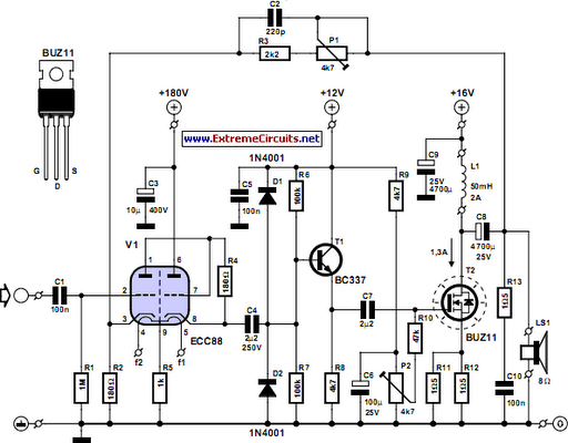
The ongoing debate regarding the superiority of valves versus transistors is not the focus here. However, for those uncertain about their choice, this simple amplifier serves as an excellent experiment. The design employs a valve as a pre-amplifier and...
Basically, this is a frequency-current converter. It is used as a frequency meter. Calibrating it can be used as a tachometer. Please be aware this is an experimental project; it wasn't connected to any vehicle, but it should work...
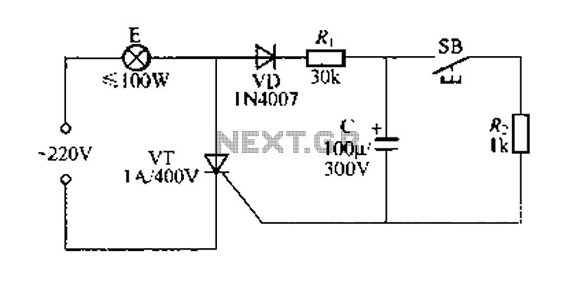
Figure 57 illustrates a simple delay lamp circuit that connects to lamp E using a two-wire connection. This design allows for the security bars to be installed directly, enabling replacement with a standard wall switch without altering the existing...
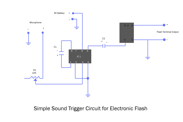
The microphone inputs connect to ground (-) and to the middle terminal of a 10K variable resistor (potentiometer), which serves as the sensitivity control. The output from the potentiometer is routed to pin 3 of the amplifier integrated circuit...
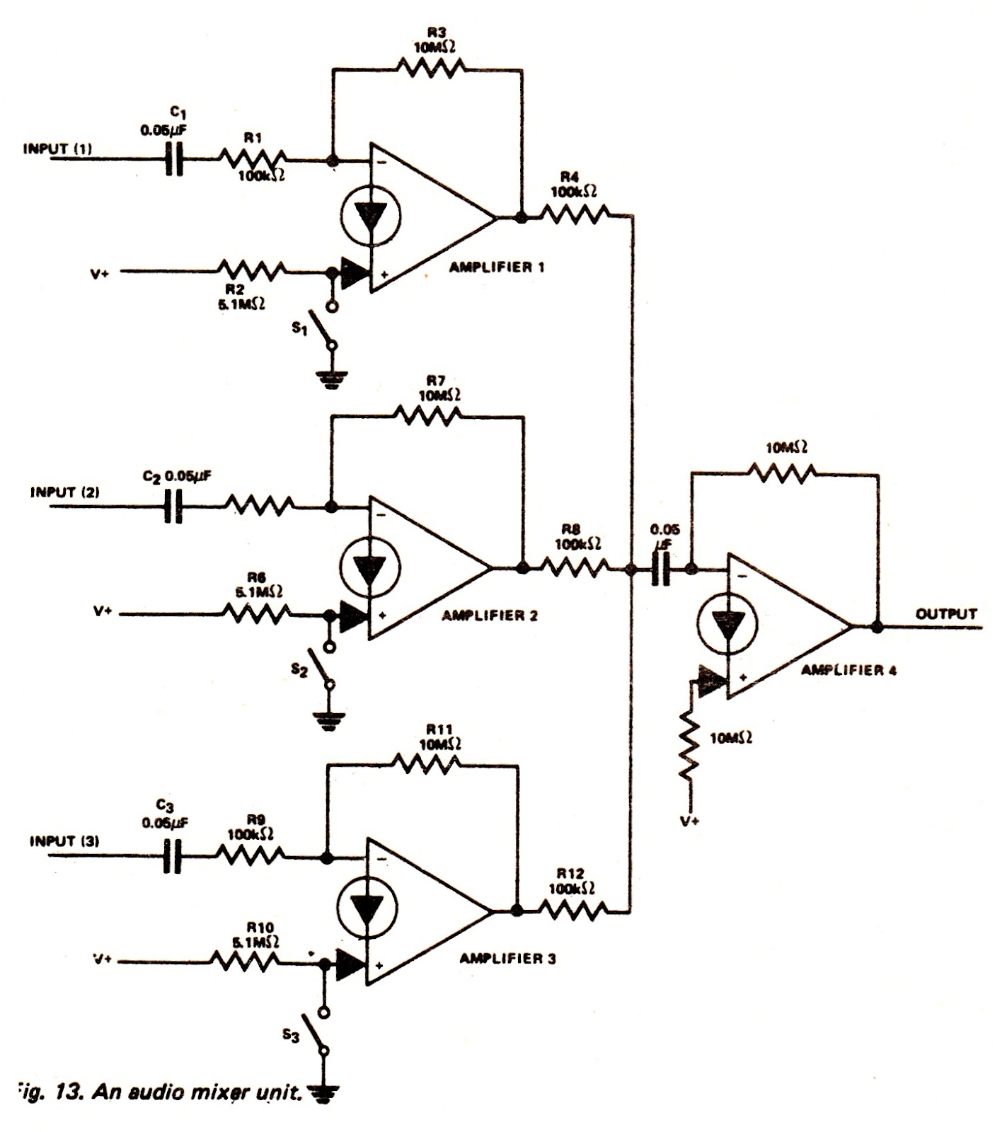
The amplifiers of an LM3900N device can be utilized to create an audio mixer unit that allows for the combination of three separate audio signals into a single composite output. The audio mixer circuit provided operates with a single...