
simple switching power supply 15 watt
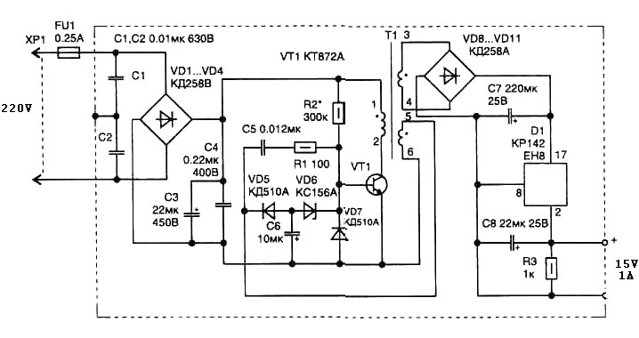
The schematic diagram is derived from a circuit designed for a simple switching power supply with a power output of 15 watts. Further details regarding this power supply and its related circuit diagram can be found on the corresponding page.
The pulse transformer T1 is a critical component in the switching power supply circuit, facilitating energy transfer between the primary and secondary windings while ensuring voltage isolation. The choice of ferrite core material, such as M2500NMS-2 or M2000NM9, is pivotal for achieving the desired magnetic properties, which influence the efficiency and performance of the transformer. The specified cross-section of 5 mm at the 5G location, combined with a central gap, optimizes the magnetic flux and minimizes core losses during operation.
The winding configuration is designed to achieve specific electrical characteristics. The primary winding, consisting of 2 turns of 0.1 mm diameter wire, is crucial for generating the initial magnetic field. The additional turns of 0.25 mm diameter wire enhance the transformer's ability to handle higher voltages and currents. The inclusion of 5-6 turns of wire identical to the primary winding serves to increase the coupling efficiency and improve the overall performance of the transformer.
In the context of the simple switching power supply, the transformer plays a vital role in converting the input voltage to the desired output voltage while maintaining regulation and minimizing ripple. The circuit design utilizes the transformer to facilitate the switching process, allowing for efficient energy conversion and management.
For a comprehensive understanding of the operation and integration of the pulse transformer within the switching power supply, it is advisable to review the complete circuit diagram and accompanying explanations provided on the designated page. This will provide insights into the overall design philosophy, component interactions, and operational principles governing the power supply system.Pulse transformer T1 is performed on the ferrite core M2500NMS-2 or M2000NM9 Sh5h5 size (cross-section of the magnetic coils at the location of 5G—5 mm with a gap in the center). Winding wire is made brand PEL-2. Winding 1. 2 turns of wire contains 600 0. 1 mm in diameter, 3-4 44 turns of 0. 25 mm diameter, 5-6 10 turns in the same wire as the primary winding. The schematic diagram come from circuit: Simple Switching Power Supply 15 Watt power supply. Go to that page to read the explanation about above power supply related circuit diagram. 🔗 External reference
Related Circuits
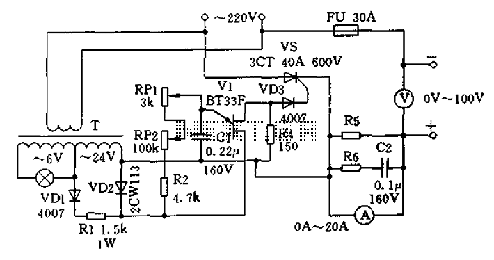
The charging apparatus depicted in the schematic circuit has a maximum output current of 20A and a maximum charging voltage of 80V. It can be adjusted starting from 0V, making it suitable for charging various types of batteries. The...

FIG M is a variable speed motor control for the opening and closing of a wicket gate. It features an electric governor. The system is activated by a power switch (SA) located on the front grid, and a toggle...
The 7815 regulates the positive supply, while the 7915 regulates the negative supply. The transformer should have a primary rating of 240/220 volts for Europe or 120 volts for North America. The center-tapped secondary coil should be rated approximately...
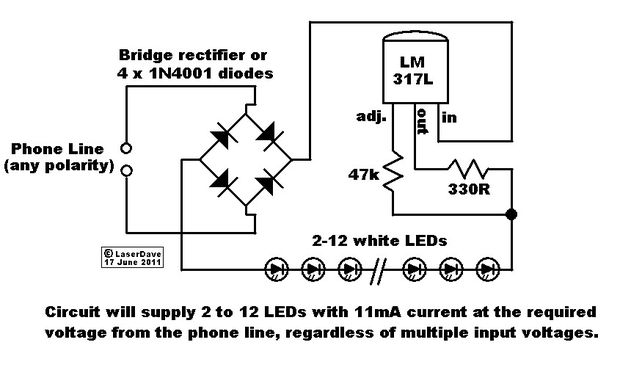
This circuit operates in a manner that allows the phone line to remain active while the LEDs are connected. When the phone is picked up, the light turns off, enabling normal phone usage. The phone line delivers 48V DC...
One 1381 part (CMOS voltage-controlled trigger available at different limits) should be selected to match the voltage across the motor (2V in this case). The other terminal of the motor is connected to a 3300µF capacitor, which is in...
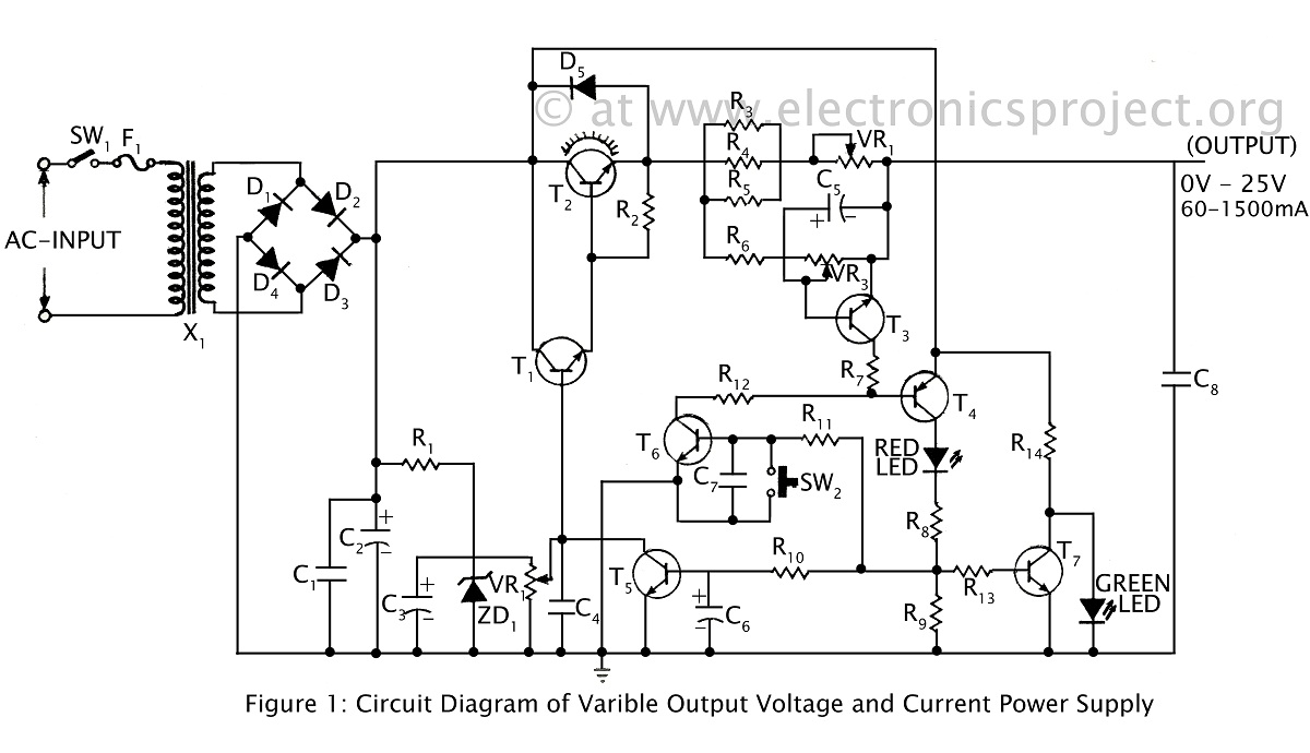
A ripple-free, short-circuit protected variable output voltage and current power supply is presented on this website as a verified project. The circuit diagram includes a description of various power supply circuits. This power supply circuit is designed to provide a...