
Simple Siren

The circuit utilizes a hex inverter integrated circuit (IC1) which contains multiple logic gates, allowing for flexibility in design and the potential to create complex sound patterns. The configuration of IC1a as a slow oscillator is pivotal; it generates a square wave output that drives the charging and discharging cycle of capacitor C1. This cyclic behavior results in a gradual change in voltage across C1, which is crucial for controlling the gate of the power MOSFET TR1.
Power MOSFET TR1 acts as a switch, modulating the power supplied to the audio oscillator circuit formed by IC1b. By adjusting the charge on C1, the duty cycle of the signal can be altered, thereby changing the effective frequency of the output sound. The audio frequency is further fine-tuned using capacitor C2 and resistor R2, which together set the resonant frequency of the sound produced. Choosing the correct values for these components is essential for achieving the desired audio characteristics and maximizing the output volume.
IC1c serves as a buffer, isolating the oscillator from the load to prevent loading effects that could distort the audio signal. This ensures that the sound produced is clean and maintains its integrity regardless of the load connected.
For applications requiring higher sound output, a piezo tweeter is recommended due to its efficiency and high sound pressure levels. Alternatively, when using an inductive sounder like a speaker, the inclusion of a series capacitor (such as 100µF) is necessary to block DC components while allowing AC signals to pass, which is essential for proper operation and sound quality.
Overall, this circuit is a compact and efficient design, capable of producing a distinctive siren sound with the flexibility to expand its capabilities through the unused gates of the hex inverter.THE circuit shown provides a smooth, piercing, wailing siren with a minimum of components. Not only this, but three spare gates of hex inverter IC1 remain, which means that a true cacophony could be created by running two sirens off the same i. c. Gate IC1a is configured as a slow oscillator which repeatedly charges and discharges capacito r C1. The charge on C1 is used to control the conductance of power MOSFET TR1, which in turn modifies the frequency of the audio oscillator formed around IC1b. IC1c serves as a buffer. The period of the siren is determined by C1 and resistor R1, and its frequency by C2 and R2. Ideally, C2 and R2 will be selected to find the resonant frequency of the piezo sounder for maximum volume.
If a piezo tweeter is used, the Simple Siren will produce an impressive volume. An inductive sounder (e. g. a speaker) may be used if a capacitor (e. g. 100F) is wired in series with it. 🔗 External reference
Related Circuits
This circuit is a simple series tone control circuit utilizing the OP-Amp LM301A. The JFET 2N3684 provides high input impedance and low noise characteristics for the feedback buffer in the op-amp-based tone control. The tone control circuit described employs an...
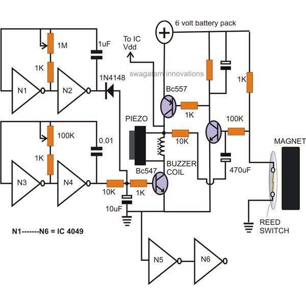
Certain circumstances and areas require the detection and securing of entrance paths through alarm systems, ensuring that whenever an individual opens an entrance door, the situation is instantly monitored by triggering an alarm. Battery-operated window and door alarms are...
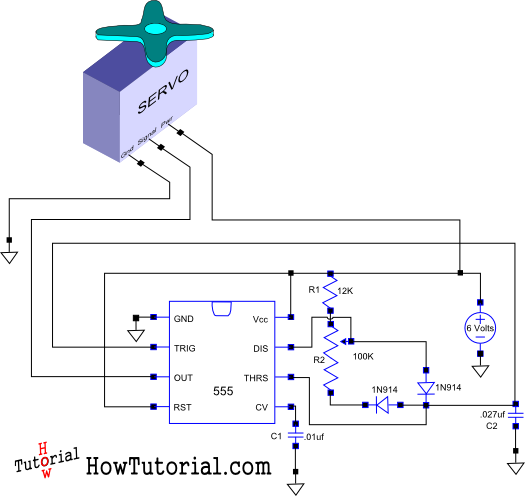
This document outlines the design of a simple circuit that enables control of a servo motor and allows for testing its functionality. The circuit for controlling a servo motor typically consists of a microcontroller, a power supply, and the servo...
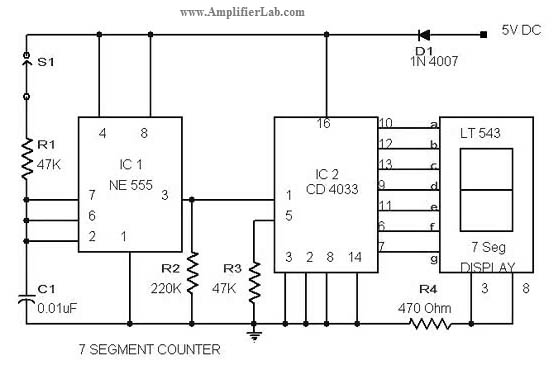
The circuit diagram of a 7-segment counter circuit has been published here. This circuit consists of the counter IC CD4033 as its central component. The 7-segment counter circuit utilizing the CD4033 integrated circuit (IC) is designed to display decimal digits...

Many people might be excited by the sound of a siren, as it is often associated with emergency events such as accidents. However, one may wonder about the underlying mechanisms that produce this alerting sound. The siren sound commonly used...
This circuit will filter out interference signals and ensure that the signal received from the Morse code station stands out. The described circuit functions as a signal processing system specifically designed to enhance the clarity of Morse code transmissions by...