
Simple Field Strength Meter
The described circuit utilizes a digital multimeter (DMM) for measuring low voltage signals, particularly in VHF applications. The choice of setting the DMM to the 200mV DC range is crucial for achieving maximum sensitivity, allowing for the detection of subtle voltage changes that may occur at high frequencies, such as those in the VHF spectrum.
The inductor L1, constructed with 7 turns on a quarter-inch former and incorporating a ferrite slug, is designed to resonate at the desired frequency range, specifically covering the UK FM band. The physical dimensions and materials used in L1 contribute to its inductance and quality factor, which are critical for effective signal reception and processing. The ferrite slug enhances the magnetic permeability of the inductor, improving its efficiency in the intended frequency range.
The advantages of utilizing a digital multimeter over an analog meter in this application cannot be overstated. The high input impedance of the DMM, typically around 10 Megohms per volt, ensures that the measurement does not load the circuit significantly, thereby preserving the integrity of the tank circuit. This is particularly important in RF applications where loading can significantly affect performance.
Additionally, the ability of a digital meter to display minute variations in signal strength provides a more precise measurement, which is essential for tuning and troubleshooting RF circuits. The improved linearity of digital meters allows for accurate readings across a wide range of signal strengths, making it easier to identify and analyze both weak and strong signals without distortion or loss of information.
Overall, the integration of a digital multimeter into this VHF circuit enhances the measurement capabilities, providing reliable and sensitive readings that are essential for effective circuit performance and analysis.The multimeter should be set to the lowest dc volts range for maximum sensitivity. This is normally 200mV DC for most meters. The circuit works well at VHF (around 100MHz) and was quite pleased with the results. L1 was 7 turns on a quarter inch former with ferrite slug. This covered the UK FM band. A digital multimeter, as opposed to an analogue s ignal meter offers several advantages in this circuit. First, the impedance of a digital meter is very high, around 10Meg/Volt on most meters. This does not shunt the tank circuit unduly. Second, compared to an analogue meter, very slight differences in signal strength can be more easily observed. Thirdly, a digital meter will have better linearity, responding well to both weak and stronger signals.
🔗 External reference
Related Circuits
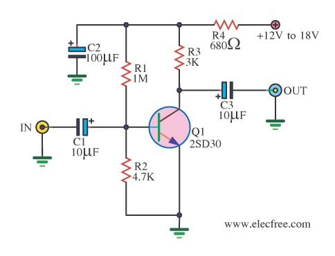
When there is a need to amplify audio signals from various sources before they reach a custom amplifier, a preamplifier (or preamp) is typically employed. This document suggests a specific circuit that is interesting due to its use of...
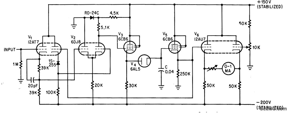
The addition of a dual-triode amplifier (V2) to a conventional peak voltmeter reduces the charging time constant while increasing the available time for measuring peak values. Linearity is maintained up to 40 volts. The integration of a dual-triode amplifier into...
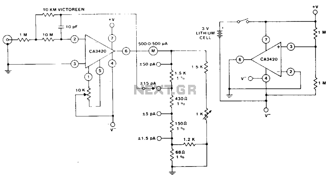
The circuit utilizes the extremely low input current (0.1 pA) of the CA3420 BiMOS operational amplifier. With only one 10 megohm resistor, it achieves a range from ±50 pA maximum to a full-scale sensitivity of ±1.5 pA. Additionally, by...
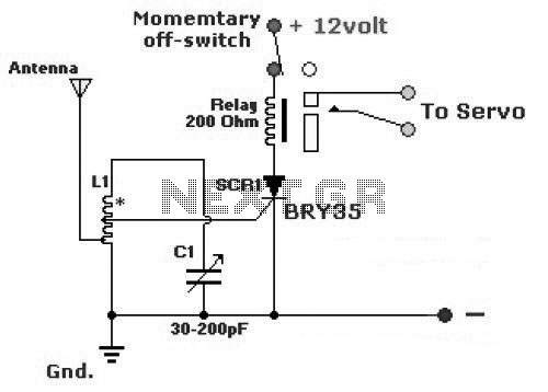
The diagram illustrates a simple and efficient receiver designed for controlling garage doors, starter motors, alarms, warning systems, and various other applications. The SCR utilized in this circuit features an exceptionally low trigger current of 30 µA. The circuit operates...
The circuit is designed to operate with an audio power amplifier that uses 18V-0V-18V power rails. The specific voltage is not critical, but the feedback is referenced to an LED chain connected to a 12V rail, necessitating a separate...
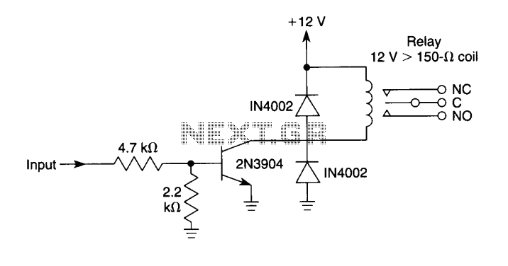
This circuit can be used to drive a 12V relay with a triggering signal of 5V. It incorporates two 1N4002 diodes, one 2N3904 transistor, and two resistors. By altering the resistor values, the input triggering voltage can be modified. The...