
simple fire alarm circuit
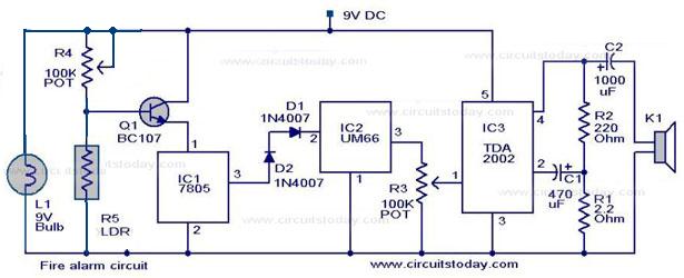
The fire alarm circuit employs an LDR as the primary sensing element, which is sensitive to changes in light intensity. The circuit is designed to be simple yet effective, making it suitable for basic fire detection applications. The LDR is positioned in such a way that it receives light from a lamp under normal conditions. When smoke is present, it scatters and absorbs light, increasing the resistance of the LDR, which leads to a rise in voltage across it.
The transistor acts as a switch in this configuration. When the voltage across the LDR exceeds a certain threshold due to increased resistance from smoke, the transistor turns ON, allowing current to flow to IC1. This integrated circuit is responsible for generating a stable 5V output, which is necessary for the operation of the tone generator IC UM66 (IC2). The UM66 is designed to produce musical tones, providing an audible alert when smoke is detected.
To ensure the sound is sufficiently loud, the output from the UM66 is fed into an audio amplifier IC, specifically the TDA 2002 (IC3). This amplifier is capable of driving a speaker, delivering a clear and audible alarm signal. The circuit's simplicity, combined with the effective use of readily available components, makes it an excellent choice for basic fire alarm systems. The design can be further enhanced with additional features such as a reset switch or a more sophisticated detection mechanism, depending on the application requirements.A simple fire alarm circuit based on a LDR and lamp pair for sensing the fire. The alarm works by sensing the smoke produced during fire. The circuit produces an audible alarm when the fire breaks out with smoke. When there is no smoke the light from the bulb will be directly falling on the LDR. The LDR resistance will be low and so the volta ge across it (below. 6V). The transistor will be OFF and nothing happens. When there is sufficient smoke to mask the light from falling on LDR, the LDR resistance increases and so do the voltage across it. Now the transistor will switch to ON. This gives power to the IC1 and it outputs 5V. This powers the tone generator IC UM66 (IC2) to play a music. This music will be amplified by IC3 (TDA 2002) to drive the speaker. 🔗 External reference
Related Circuits

In a concrete circuit relay application, the transistor VT functions as a high-speed, high-voltage switch. The voltage requirement for switching is 5 to 10 times the rated voltage of the solenoid valve. The circuit is designed for a fast...

This paragraph describes an easy car alarm circuit that utilizes fewer components and is simple to produce. The circuit consists of an automobile anti-theft alarm system based on the NE555 timer, a power switch (VT), and a switch (S2),...
S1 is a power switch. U2 drives counter U3 by producing a pulse when S2 is depressed. U4 and DISP1 read the count of counter IC U3. S3 is a reset to zero switch. The counter is a basic...
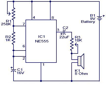
This weblog focuses on electronic circuit schematics, PCB design, DIY kits, and diagrams for electronic projects. A simple circuit utilizing the NE555 IC is presented, which can be employed to generate metronomes. This circuit is particularly beneficial for music...
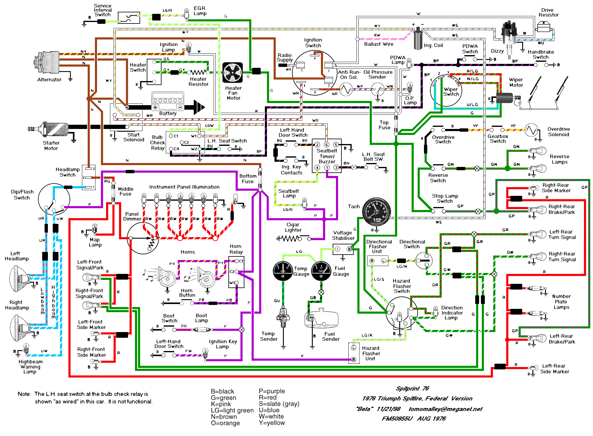
The Haynes manual is quite confusing regarding the labeling of relays on Spitfires. The two main sources of confusion are: 1. The illustrations depict right-hand drive cars with different relay locations, and 2. The naming of the relays is...

A typical laptop power adapter circuit converts an AC input of 22V through a rectifier and filter circuit to produce an output of +30V DC. This voltage is then processed by a switch oscillation circuit (U1, UCC38050P), which controls...
Warning: include(partials/cookie-banner.php): Failed to open stream: Permission denied in /var/www/html/nextgr/view-circuit.php on line 713
Warning: include(): Failed opening 'partials/cookie-banner.php' for inclusion (include_path='.:/usr/share/php') in /var/www/html/nextgr/view-circuit.php on line 713