
Simple RF Detector for 2 m
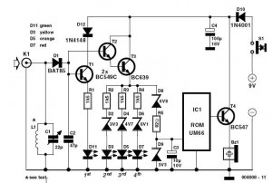
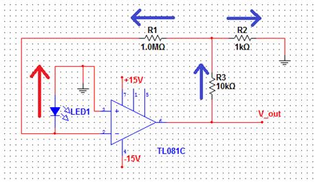
This circuit is designed to identify and measure radio frequency (RF) radiation emissions, which can indicate issues such as faulty connections, damaged cables, or insufficient shielding in electronic devices. The core component of the circuit is a sensitive RF detector, typically implemented using a diode or a specialized RF sensor module.
The circuit operates by capturing the RF signals present in the environment and converting them into a measurable voltage output. This output can then be displayed on an analog or digital meter, allowing the user to assess the level of RF radiation.
To enhance the sensitivity and accuracy of the measurements, the circuit may include additional components such as amplifiers, filters, and capacitors. An operational amplifier can be used to boost the signal strength, while a band-pass filter can help isolate the frequency range of interest, eliminating unwanted noise from other sources.
Furthermore, the design may incorporate a microcontroller to process the detected signals, providing a more sophisticated analysis of the RF emissions. The microcontroller can be programmed to trigger alarms or visual indicators when radiation levels exceed predefined thresholds, making the circuit not only a diagnostic tool but also a safety device.
Power supply considerations are also crucial; the circuit can be powered by batteries for portability or connected to a stable power source for continuous monitoring. Proper grounding and shielding techniques should be employed in the circuit layout to prevent interference and ensure accurate readings.
Overall, this RF radiation detection circuit serves as an essential tool for troubleshooting and maintaining the integrity of RF equipment, ensuring compliance with safety standards and optimal performance.This simple circuit helps you sniff out RF radiation leaking from your transmitter, improper joints, a broken cable or equipment with poor RF shielding. Th. 🔗 External reference
Related Circuits
A sawtooth wave generator circuit using a 555 IC is presented in the article below. The frequency equation is provided with the supply voltage Vcc. The sawtooth wave generator circuit utilizing a 555 timer integrated circuit (IC) is a fundamental...
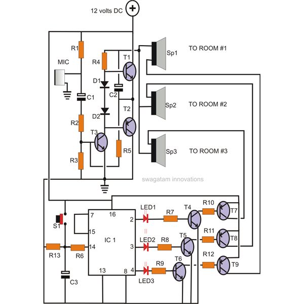
A home intercom system can be constructed using a versatile circuit design. This system allows communication across up to ten different locations or rooms discreetly. It utilizes a single changeover switch for selecting the desired location, replacing the traditional...
This is the basic interface I used as part of my Computerized Room project. This is the parallel interface only. The 8 bit input card can be found, along with the rest of the project, at Computerize Your Room/House....
The circuit diagram of the Lie Detector is shown above. It consists of three transistors (TR1 to TR3), a capacitor (C1), two lights or LEDs (L1 & L2), five resistors (R1 to R5), and a variable resistor (VR1). This circuit...
This circuit is useful in liquids level or proximity detection. It operates detecting the distance from the target by reflection of an infra-red beam. It can safely detect the level of a liquid in a tank without any contact...
The comparator output drives an LED, and the next step is to sense the intensity of the LED. This lab involves building a light detector circuit using an operational amplifier (op-amp) and a standard light-emitting diode (LED). It is...
Warning: include(partials/cookie-banner.php): Failed to open stream: Permission denied in /var/www/html/nextgr/view-circuit.php on line 713
Warning: include(): Failed opening 'partials/cookie-banner.php' for inclusion (include_path='.:/usr/share/php') in /var/www/html/nextgr/view-circuit.php on line 713