
Simple FM Radio with improved audio gain
To create an inductor using solid wire, begin by winding six turns of the wire around a cylindrical object, such as a pen or pencil, which should have a diameter of approximately 0.5 inches. After completing the winding process, carefully remove the coil from the cylindrical form. The next step involves gently spreading the coils apart to achieve a total length of approximately 0.75 inches.
Once the coil is properly shaped, the component labeled C2 should be soldered to the coil. The placement of C2 is critical; it should be positioned near the center of the coil to ensure optimal electrical performance. This configuration allows for effective inductance, which can be utilized in various electronic applications, such as filters, oscillators, or power supply circuits.
The solid wire used for winding should be of an appropriate gauge to handle the current requirements of the circuit while minimizing resistive losses. Additionally, the number of turns and the spacing between them can influence the inductance value, which can be calculated using the formula for inductance based on the coil's physical dimensions and the properties of the wire material. Proper insulation should be considered to prevent short circuits, especially if the coil is to be placed in a compact enclosure with other components.Wind 6 turns of solid wire on a pen or pencil that is just under 1/2 inch in diameter. Remove the wire from the pencil and spread the winding to make a length of 3/4 inch. Solder C2 somewhere near the middle of the coil. 🔗 External reference
Related Circuits
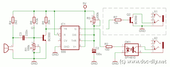
This article describes how to build a simple yet effective sound trigger for cameras or flashes. The circuit allows for experimentation with high-speed photography. The sound trigger circuit is designed to activate a camera or flash unit in response to...

Here is some experimental hardware and software to transmit and receive AX.25 packets. It is essentially a PIC-E clone designed around a Atmel AT90S2313 with a few extra bells and whistles. I had picked up a couple of MXCOM...
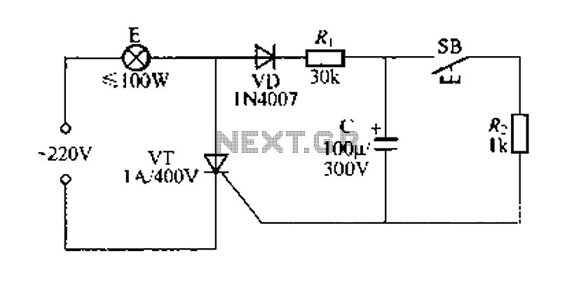
Figure 57 illustrates a simple delay lamp circuit that connects to lamp E using a two-wire connection. This design allows for the security bars to be installed directly, enabling replacement with a standard wall switch without altering the existing...
The circuit operates by adjusting the firing angle of the Triac. Resistors R1, R2, and capacitor C2 are involved in this process. The firing angle can be modified by changing the value of any of these components, with R1...
This is the first oscillator that was built. Various resources such as books, magazines, and online schematics were reviewed. Most of the designs encountered were either Colpitts or Hartley oscillators. While these designs are relatively straightforward, they require specific...
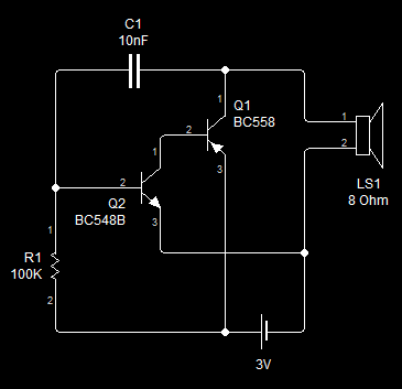
This circuit is similar to the previous one but employs positive feedback to enhance the amplitude delivered to the speaker. It is adapted from a small 5-transistor radio that utilizes a 25-ohm speaker. In the earlier circuit, the load...