
Simple Surround Sound Decoder
The simple surround sound decoder utilizes the Hafler principle to create an immersive audio experience by processing stereo signals to produce surround sound. This circuit typically employs a few key components, including operational amplifiers, resistors, and capacitors, to achieve the desired audio effect.
The core of the circuit is an operational amplifier configured to mix the left and right audio channels. The output from this stage is then fed into additional circuitry designed to create the surround sound effect. This is accomplished by manipulating the phase and amplitude of the audio signals, allowing for the creation of virtual surround channels that enhance the listening experience.
Resistors are strategically placed to control the gain of the audio signals, ensuring that the output levels are balanced and suitable for driving speakers. Capacitors may be used for filtering purposes, helping to eliminate unwanted noise and ensuring that the audio output is clean and clear.
In terms of layout, the circuit should be designed to minimize interference and maintain signal integrity. This can be achieved by keeping signal paths short and using proper grounding techniques. Additionally, the power supply should be stable and adequately filtered to prevent hum and noise from affecting the audio quality.
Overall, the simple surround sound decoder based on the Hafler principle represents an effective solution for enhancing audio playback in various applications, from home theater systems to music production environments. Its relatively straightforward design allows for ease of implementation while delivering a significant improvement in audio immersion.Simple Surround Sound Decoder. Introduction This surround-sound decoder is based on the Hafler principle, first discovered by David Hafler sometime in the early 1970s. The original idea. 🔗 External reference
Related Circuits
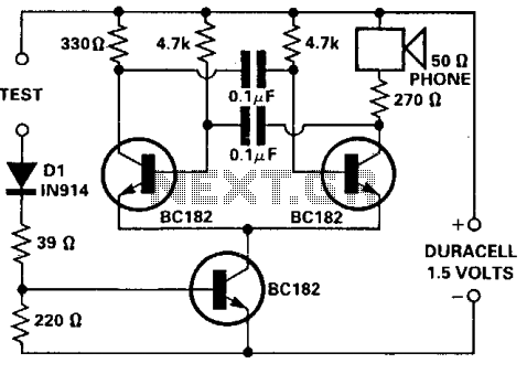
This tester is designed for tracing wiring on Printed Circuit Boards (PCBs). Resistors below 50 ohms function as a short circuit, while those above 100 ohms behave as an open circuit. The circuit utilizes a simple multivibrator activated by...

The circuit utilizes a dual operational amplifier integrated circuit (IC), specifically the 1458, which contains two separate op-amps within a single package. In this configuration, the first op-amp functions as a voltage follower, directing its output to charge capacitor...

The operation of the circuit is divided into three parts: low-frequency production, high-frequency manufacturing, and low-frequency extension. The low-frequency signal is generated from IC1, which is connected to an astable multivibrator circuit. The frequency is determined by the resistor...
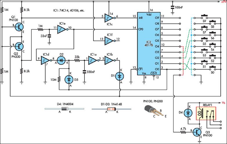
This simple combination lock accommodates codes from 1 to 9 digits long, with the only restriction being that the same digit cannot be used twice. The circuit is designed for a 4-digit code, illustrated by the example "2057". Any...
The 220-240V AC mains source is stepped down to 9V AC by transformer X1. The transformer output is rectified by diodes D1 through D4 connected in a bridge configuration, with the positive DC voltage wired directly to the charger's...
A simple variable frequency oscillator utilizing a 555 timer IC to generate a square wave frequency that can be adjusted using a potentiometer. The circuit operates primarily on the principles of astable multivibrator configuration using the 555 timer IC, which...
Warning: include(partials/cookie-banner.php): Failed to open stream: Permission denied in /var/www/html/nextgr/view-circuit.php on line 713
Warning: include(): Failed opening 'partials/cookie-banner.php' for inclusion (include_path='.:/usr/share/php') in /var/www/html/nextgr/view-circuit.php on line 713