
Simple Lcd Display Power Supply
The circuit described is a sophisticated implementation designed to provide a negative voltage supply for large-screen LCDs in laptop computers, ensuring optimal display performance. The switching regulator operates efficiently by converting the positive battery voltage into a variable negative voltage, which is crucial for achieving the desired contrast levels in LCD displays.
The use of a 4-bit Digital-to-Analog Converter (DAC) allows for fine-tuning of the output voltage, providing a range from -6.5 V to -11.5 V. This capability is essential for adapting to varying display requirements and ensuring that the LCD operates within its specified voltage range. The DAC's output is controlled by a microprocessor, which can dynamically adjust the voltage based on real-time requirements, enhancing the overall user experience.
The integration of a 74 HC-series CMOS gate for DAC implementation ensures that the circuit benefits from rail-to-rail output capability, allowing for maximum voltage swing and improved performance. The resistor divider network, which includes a 240-kΩ resistor, plays a critical role in setting the reference voltage for the regulator. The MAX635 regulator maintains the voltage at the junction of the resistor divider at 0 V, providing a stable reference point for the operation of the switching regulator.
The switching regulator's operation is contingent upon the feedback voltage at the VFb pin. When this voltage exceeds ground, the regulator engages, allowing energy to be stored in the -V filter capacitor via the inductor. This energy storage is vital for maintaining a stable negative voltage output. Conversely, if the feedback voltage drops below ground, the regulator enters a skip cycle mode to prevent excessive voltage drop, thereby maintaining the integrity of the output voltage.
The design also incorporates power-saving features, allowing the circuit to enter a low-power mode by interrupting the ground pin. This functionality is particularly beneficial in portable devices, where battery life is a critical consideration. The circuit's current draw of less than 150 mA further emphasizes its efficiency, making it suitable for battery-operated applications.
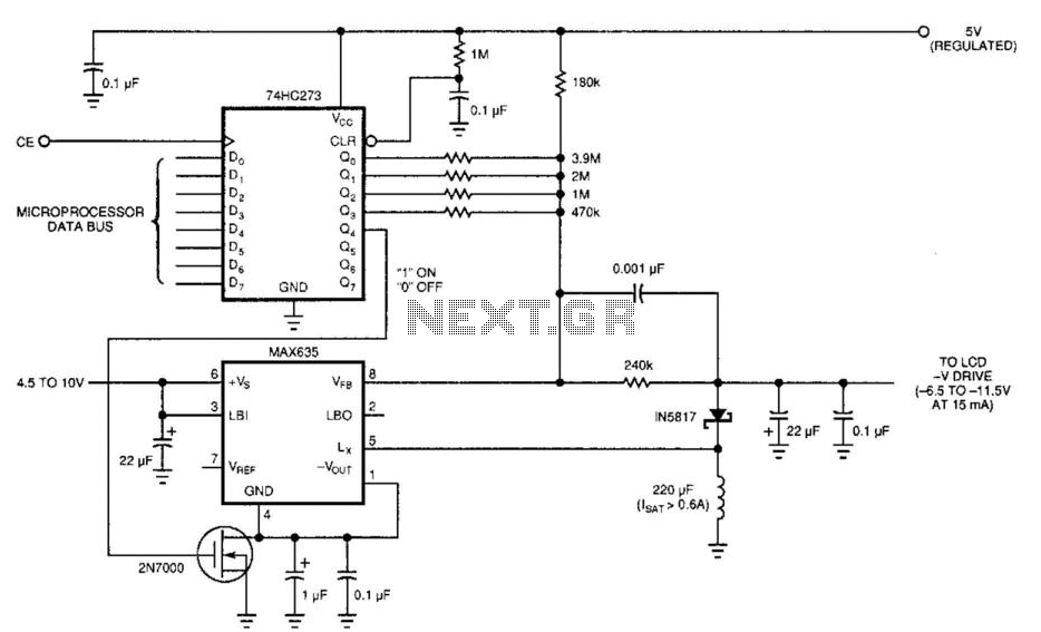
Overall, this circuit exemplifies an effective solution for generating a variable negative voltage supply for LCD displays, combining advanced components and design strategies to achieve reliable performance while minimizing power consumption. Laptop computers often use large-screen LCDs, which require a variable and a negative supply to ensure maxi mum contrast. This circuit operates from the system"s positive battery supply and generates a digitally variable negative voltage to drive the display. This figure"s switching regulator creates a negative voltage from the battery supply. The microprocessor data bus drives a 4-bit DAC, which in turn varies the actual regulator output from - 6.5 to -11.5 V.
This arrangement allows a staircase of 16 possible voltages between these limits. The circuit implements the DAC by using the rail-to-rail output-drive capability of a 74 HC-series CMOS gate. A resistor divider network formed by the 240-kfi resistor, connected to the -V filter capacitor and the resistors, is referenced to the 5-V supply control (the MAX635 regulator).
When the voltage at the VFb pin is greater than ground, the switching regulator turns on. The inductor dumps this energy into the -V filter capacitor. When the voltage at VFb is less than ground, the regulator skips a cycle. The MAX635 regulates the voltage at the junction of the resistor divider to 0 V. Thus, any resistor that the DAC connects to ground (logic 0) will not contribute any current to the ladder. Only the resistors that are at 5 V (logic 1) will be part of the voltage-divider equation. The entire switching-regulator supply draws less than 150 . You can place the circuit in an even lower power mode by interrupting the ground pin. The high-current path is from the battery input through the internal power PMOSFET to the external inductor.
Disconnecting the ground connection simply disables the gate drive to the FET and turns off the internal oscillator. 🔗 External reference
Related Circuits
This simple circuit is started running by connecting a twelve volt battery across the terminals, causing the large diameter Light-Emitting Diode to light up. When the battery is removed, the LED stays lit up because the circuit has become...
More: An electronic schematic is a representation of the components and connections within an electronic circuit. It serves as a blueprint for constructing electronic devices, allowing engineers and technicians to visualize how components interact and function together. The schematic...
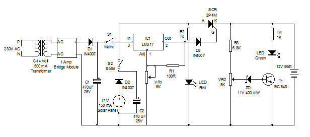
Battery charger utilizing solar and electrical power with a circuit diagram. This dual power source battery charger can charge a lead-acid battery using two different power sources. The battery charger circuit is designed to efficiently charge a lead-acid battery by...
A power supply circuit designed to operate within a voltage range of 6 to 15V, providing a current output of 500mA. This circuit includes an adjustable amplification segment and utilizes a composite transistor configuration for its power supply. The described...
A step-down circuit is utilized to approximately halve the RMS voltage between the line input and the inductive load (L1), as illustrated in the circuit diagram below. A turn-on delay of about 7 ms is achieved through the combination...
This simple circuit generates a good and stable 1V peak-to-peak square wave at 100Hz, 1KHz and 10KHz using a single 1.5V cell as power supply. An useful feature of this circuit is that frequency changes can be obtained by...
Warning: include(partials/cookie-banner.php): Failed to open stream: Permission denied in /var/www/html/nextgr/view-circuit.php on line 713
Warning: include(): Failed opening 'partials/cookie-banner.php' for inclusion (include_path='.:/usr/share/php') in /var/www/html/nextgr/view-circuit.php on line 713