
Simple LF converter
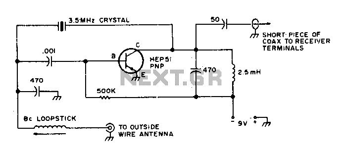
The described converter is designed to facilitate the reception of signals within a specified frequency range, specifically from 25 kHz to 500 kHz. The use of a short coaxial cable is crucial for minimizing signal loss and ensuring optimal performance when connecting the converter to the receiver's antenna input.
To effectively utilize the converter, the user must set the receiver to a frequency of 3 MHz. This initial setting allows the user to calibrate the receiver by adjusting for the strongest signal from a crystal calibrator, which serves as a reference point. Following this calibration, the user can then incrementally tune the receiver to higher frequencies, which correspond to specific lower frequency ranges. For instance, maintaining the receiver at 3 MHz aligns with a 200 kHz output, while further adjustments will yield 300 kHz and 500 kHz outputs. Notably, tuning the receiver to 4 MHz also provides a 500 kHz output, showcasing the versatility of the converter in accessing multiple frequency ranges with a single tuning adjustment.
This operational method highlights the importance of precise tuning and calibration in achieving effective signal reception across the defined frequency spectrum. The converter's design and recommended operational procedures ensure that users can efficiently access and utilize the lower frequency ranges for various applications, such as communication or signal analysis.This converter allows coverage from 25 kHz up to 500 kHz. Use short coax from the converter to receiver antenna input Tune the receiver to 3 MHz, peak for loudest crystal calibrator and tune your receiver higher in frequency to 3 MHz and you"re tuning the 100 kHz range. 3 MHz puts you at 200 kHz, 3 MHz equals 300 kHz, 3 MHz yields 500 kHz, and 4 MHz gives you 500 kHz. 🔗 External reference
Related Circuits
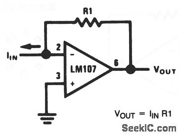
This basic circuit feeds the input current directly into the summing node (pin 2), causing the op-amp output to adjust and extract the same current from the summing node through resistor R1. The scale factor of the circuit is...
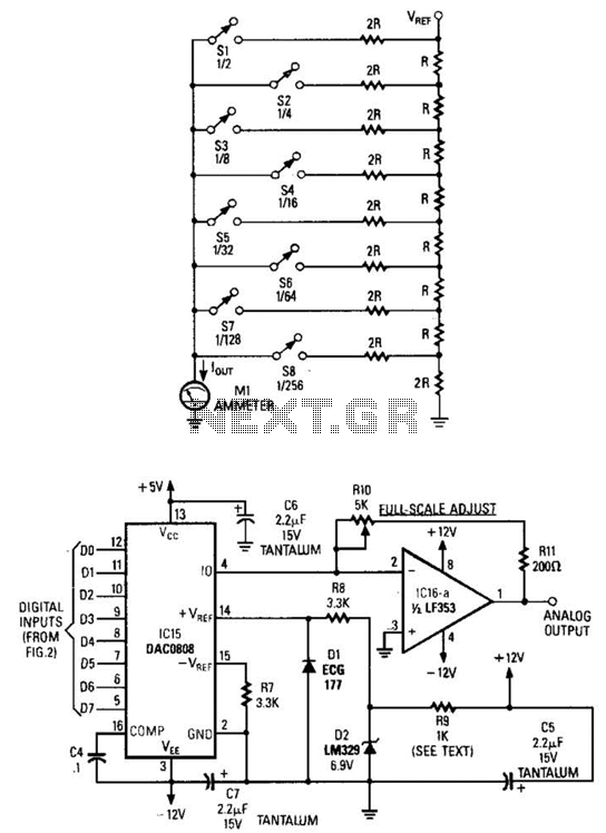
Figure A illustrates an R/2R resistor ladder. Each closed switch increases the current flow. A basic channel A/D converter is depicted in Figure B. The voltage reference (D2) is shared across all channels, although the value of the dropping...
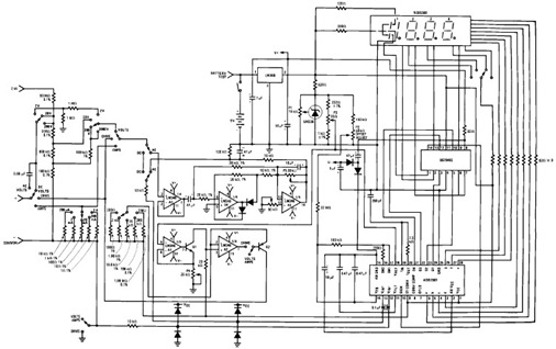
The following circuit illustrates the design of a simple digital multimeter circuit diagram. This circuit employs the ADD3501. Features include the combination of voltage measurements, among others. The circuit design for a simple digital multimeter utilizing the ADD3501 integrates several...
This characterization circuit, along with a PC and specific software, accurately measures the complete discharge cycle of a rechargeable AA cell. The capacity and output resistance of the cell can be easily determined from the resulting curve of these...
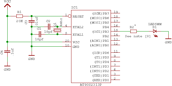
The GNU tools must be configured, built, and installed on the system. This chapter presents a simple example of using the GNU tools in an AVR project. After reviewing this chapter, users should gain a better understanding of how...
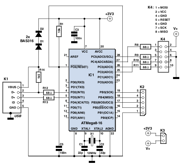
In the past, it was straightforward to utilize the parallel port of a standard PC to program various types of AVR microcontrollers. Currently, one must purchase a programmer that connects to the PC via USB, which increases the complexity...