
simple usb avr isp compatible programmer
This circuit design offers a practical solution for programming AVR microcontrollers without the need for expensive hardware. The use of a standard AVR microcontroller, combined with a minimal number of passive components, makes the design cost-effective and accessible. The firmware's implementation of a USB interface allows for seamless integration with modern PCs, enabling the microcontroller to be recognized as a serial device. This functionality is critical for developers using AVR Studio, as it allows for straightforward programming and debugging of the microcontroller.
The DIP-28 package of the AVR microcontroller is particularly advantageous for prototyping, as it is compatible with both breadboards and prototyping boards, facilitating easy assembly and testing. The inclusion of connector K2 for programming underscores the circuit's versatility, allowing for direct access to the microcontroller for firmware updates or modifications. Proper configuration of the fuses to utilize the external crystal oscillator is crucial for ensuring reliable operation of the microcontroller, particularly in applications requiring precise timing.
Jumper K3 provides an optional method for powering the circuit from the USB port, although caution is advised when using this feature. Powering the circuit in this manner may introduce noise or instability, which could affect the programming process. Therefore, it is recommended to use an external power source whenever possible. The 10-way box header K4 conforms to Atmel's standard pinout, ensuring compatibility with other Atmel devices and facilitating easy connections to additional peripherals or programming tools.
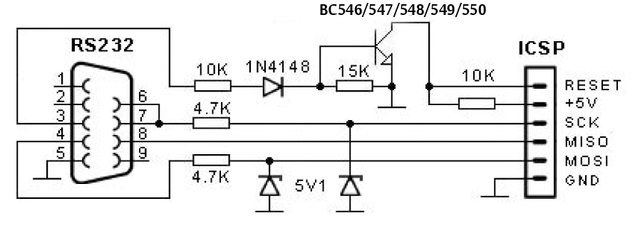
Overall, this circuit exemplifies an innovative approach to bridging the gap between older programming methods and modern USB interfaces, making it an invaluable resource for hobbyists and professionals working with AVR microcontrollers.In the old days it was very simple to use the parallel port of a standard PC and program just about any type of AVR microcontroller with it. When you want to do that now, you`re first obliged to buy aprogrammer that communicates with the PC via USB, which immediately raises the threshold of getting started with these microcontrollers.
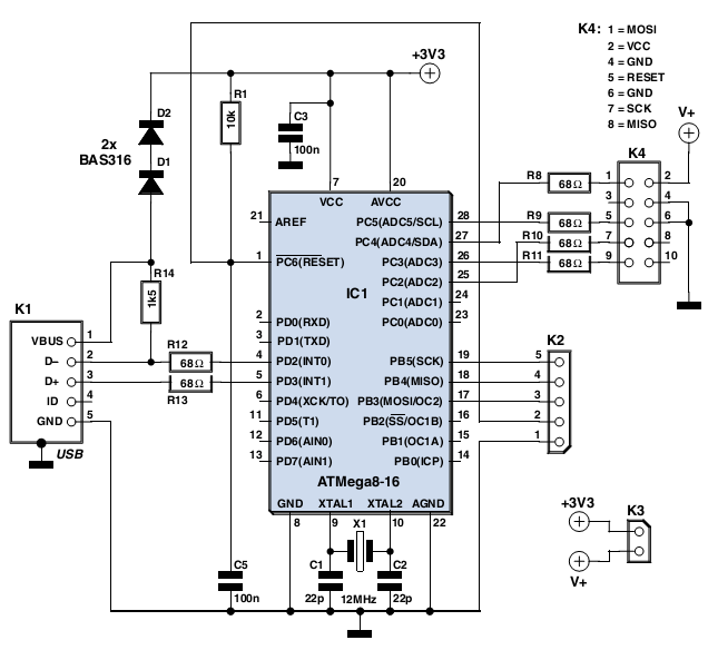
The circuit presented here offers a solution to this. As you can see from the schematic, this is a very simple circuit, built around a cheap, standard AVR microcontroller plus a handful of passive components. You may have already observed that this microcontroller does not have a USB interface and the circuit does not use a USB to serial converter either.
The strength of this circuit is found in the firmware. The USB interface has been implemented in software, as we have shown in an earlier article AVR drives USB` in the March 2007 issue. The firmware ensures that the circuit is recognised by the PC as a serial port and communicates with AVR Studio, the standard Atmel development environment, as if it were a real` AVR-ISP programmer.
The circuit is easily built on a small piece of prototyping board or even on a bread board, since the controller is available in a DIP-28 package. If you are going to pro-gram the controller yourself (via connector K2) then make sure that you set the configuration fuses so that the internal oscillator uses the external crystal as the clock source.
Jumper K3 is provided in the event you would like to power the circuit to be programmed from the USB port. We do not recommend that you do this, however, but sometimes there is no other option. K4 is a 10-way box header which has the same standard pinout that Atmel uses everywhere. 🔗 External reference
Related Circuits
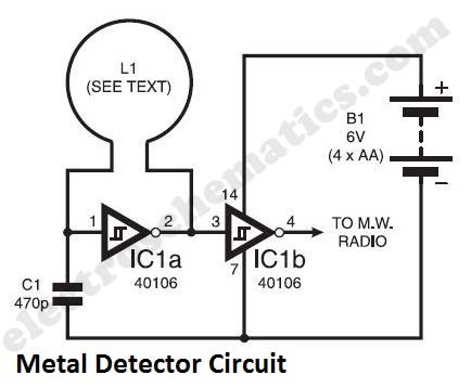
The metal detector circuit presented here exemplifies simplicity while demonstrating effective functionality. It utilizes a single 40106 hex Schmitt inverter IC, a capacitor, a search coil, and batteries. A connection from IC1b pin 4 must be made to a...
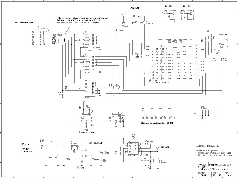
This GAL programmer is controlled via a parallel port, so that any exclusive interface is not required for the programmer. It is easy to use on the notebook PCs. When programming a PIC, a socket converter is needed. After...
The computer needs at least 180 millivolts peak-to-peak and the condenser microphone in my headset produces about 20 millivolts peak-to-peak into a 2.2k load with normal speech levels. There are USB ports on the machines, so I can use...
The entire AVR programmer has been built using common parts and fits in the case of the serial connector. The socket PCB has been created to accommodate a 28-DIP AVR ATmega8 microcontroller, but a socket PCB can be designed...
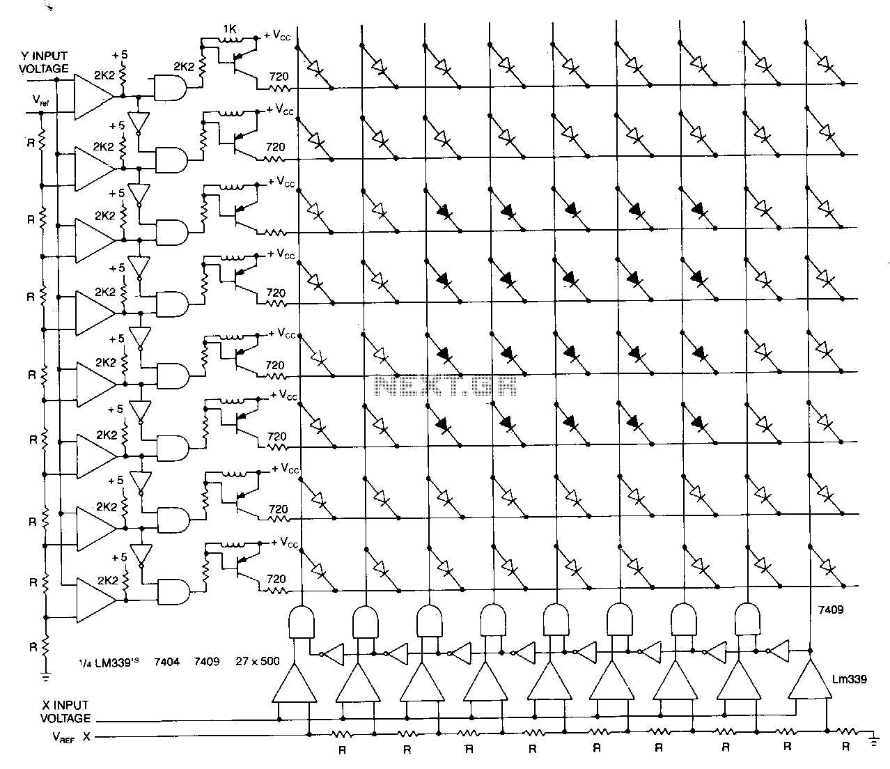
This matrix can display the values of two variables, such as frequency and voltage. The display consists of a graph made from a matrix of LEDs. The LEDs on each axis are color-coded: red indicates out of tolerance, while...
In previous discussions, it was mentioned that several ATMEL ATMEGA16 processors were resoldered. A decision was made to create a useful application utilizing this microcontroller. Given that this controller offers increased ROM and RAM capacity, high-level programming in C...
Warning: include(partials/cookie-banner.php): Failed to open stream: Permission denied in /var/www/html/nextgr/view-circuit.php on line 713
Warning: include(): Failed opening 'partials/cookie-banner.php' for inclusion (include_path='.:/usr/share/php') in /var/www/html/nextgr/view-circuit.php on line 713