
Simple vu meter schematic
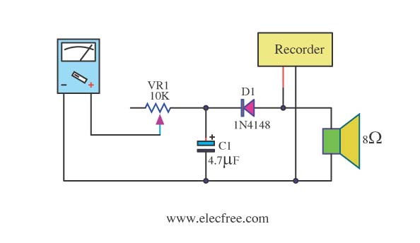
The described circuit presents a practical solution for integrating a VU meter into audio systems that lack this feature. The use of a multimeter provides a cost-effective alternative to traditional VU meters, particularly in radio tape players where space and functionality may be limited. The incorporation of a 100µA range allows for accurate readings of low current levels, which is essential for monitoring audio signals without distortion.
The inclusion of a 10kΩ potentiometer enables fine-tuning of the meter's response, ensuring that the circuit can adapt to various audio signals. This adjustment is crucial for achieving optimal performance, particularly when dealing with fluctuating audio levels. The rectification process, performed by the diodes and capacitors, converts AC signals from the audio source into DC, making them suitable for measurement by the multimeter.
Once the power amplifier circuit is assembled, the integration of this VU meter circuit can be accomplished seamlessly, providing real-time monitoring of audio output levels. The CA310 IC is a key component that enhances the circuit's sensitivity, allowing it to detect subtle changes in audio signals. This feature is particularly beneficial for audio engineers and hobbyists who require precise monitoring capabilities.
The circuit's simplicity is a notable advantage, as it minimizes the need for extensive electronic knowledge or complex assembly processes. With only a few additional components required, the circuit can be constructed quickly, making it accessible for those looking to enhance their audio equipment without significant investment. The use of VR1 for sensitivity adjustment further adds to the user-friendly nature of the design, allowing for customization based on individual preferences or specific audio environments.
Overall, this circuit represents a valuable addition to audio systems, providing functionality that enhances the listening experience while maintaining ease of use and affordability.Expensive stereo is general often have VU meter come to and for help show max power the stereo not too much. For radio tape general plaything has will no VU Meter. I then think to seek Multi meter use can replace. By use Range 100uA and electronics equipment the other again. It have be Potentiometer 10KHZ for fine decorate the rapidity the value d eviates full scale. Part diode and Capacitors perform arrange the electric current rectifier from AC to DC Current. Usability easily by you build to straddle at internal monitor speaker immediately. When build power Amplifier Circuit finished already. Many you might something Peak Reading VU Meter circuits. I begs for to advise this circuit, be one your choice. By it uses IC CA310, make have high sensitive, show with Current Meter. Get comfortable besides this circuit still use the a little equipment and build easy as well. For VR1 use for fine decorate the sensitive of this. Give can signal sound temple, very low volt, get sir. Detail other part please see in like model the circuit is sir. Read More 🔗 External reference
Related Circuits
Simple homemade oscilloscopes are not difficult to design and build. Various designs dating back to the 1930s have been studied, leading to the development of a simple oscilloscope that electronics hobbyists can construct using readily available parts today. The...
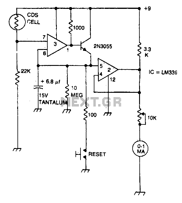
A strobe light meter captures the peak flash intensity and retains it long enough to provide a reading. The reset button must be pressed prior to each measurement. The strobe light meter operates by detecting the peak intensity of light...
The circuit is connected in parallel with the output of a power amplifier and provides the signal level from the output. By adjusting the resistance R1 in the input circuit, the power indication can be adapted to the resistance...
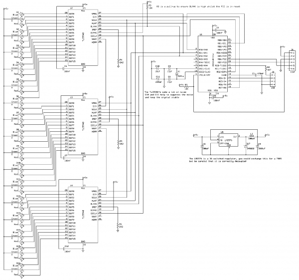
This project creates an RGB LED VU Meter controlled via USB by a host machine running Windows 7 or Vista. It serves multiple purposes: it demonstrates the ability to read audio information from the Windows machine and transmit it...
The 220-240V AC mains source is stepped down to 9V AC by transformer X1. The transformer output is rectified by diodes D1 through D4 connected in a bridge configuration, with the positive DC voltage wired directly to the charger's...
The primary issue with the design of a stereo amplifier that includes a total bass driver is that the signals from the left and right channels eventually become combined. This summation process minimizes the separation between channels, compromising the...