
Simple crowbar
The overvoltage protection circuit is a critical component in safeguarding sensitive electronic devices from voltage spikes that could lead to catastrophic failures. The circuit typically comprises a zener diode, a transistor, and a thyristor, each playing a vital role in the operation of the protection mechanism.
The zener diode is selected based on the desired clamping voltage, which should correspond to the maximum allowable voltage for the application. When the input voltage exceeds this threshold, the zener diode conducts, allowing current to flow into the base of the transistor. This action turns on the transistor, which, in turn, triggers the thyristor. The thyristor acts as a switch that effectively short circuits the supply voltage, diverting the excess current away from the load and protecting the downstream components.
The selection of the thyristor is crucial; it must be rated for a current level that is at least twice the expected short circuit current to ensure reliable operation during fault conditions. Additionally, the thyristor's voltage rating must exceed the maximum voltage of the supply to prevent breakdown during operation.
In applications where the protection circuit is integrated with a fuse, it is essential to connect the thyristor in such a way that it operates in conjunction with the fuse, providing an additional layer of safety. This configuration ensures that, in the event of an overvoltage condition, the thyristor will activate before the fuse blows, thereby minimizing the risk of damage to the connected loads.
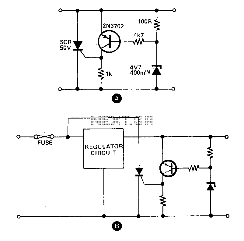
Resetting the circuit can be achieved through two methods: either by switching off the power supply, which cuts off the current flow and allows the thyristor to turn off, or by introducing a switch to break the thyristor circuit, thus allowing for manual reset. This design allows for efficient recovery from overvoltage conditions, ensuring the continued operation of the electronic system while maintaining the integrity of sensitive components.These circuits provide overvoltage protection in case of voltage regulator failure or application of an external voltage. Intended to be used with a supply offering some form of short circuit protection, either foldback, current limiting, or a simple fuse.
The most likely application is a 5 V logic supply, since TTL is easily damaged by excess voltage. The values chosen in A are for a 5 V supply, although any supply up to about 25 V can be protected by simply choosing the appropriate zener diode. When the supply voltage exceeds the zener voltage +0 V, the transistor turns on and fires the thyristor
This shorts out the supply, and prevents the voltage rising any further. In the case of a supply with only fuse protection, it is better to connect the thyristor the regulator circuit when the crowbar operates. The thyristor should have a current rating about twice the expected short circuit current and a maximum voltage greater than the supply voltage.
The circuit can be reset by either switching off the supply, or by breaking the thyristor circuit with a switch. 🔗 External reference
Related Circuits

FIG IC, ICR, Ri, R, and AN composition form a bistable contact circuit with a Ge transistor. It includes components such as ICc, lc, c2, and Dj, and is associated with a one-shot delay circuit. The circuit can be...
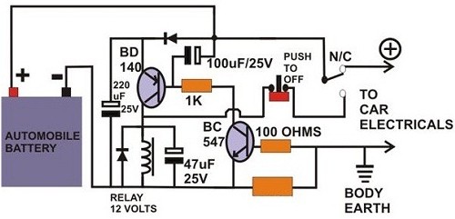
A circuit breaker is an electronic device that functions to protect an electrical circuit from hazards or damage caused by overloads or short circuits. A circuit breaker operates by automatically interrupting the flow of electricity when it detects an...
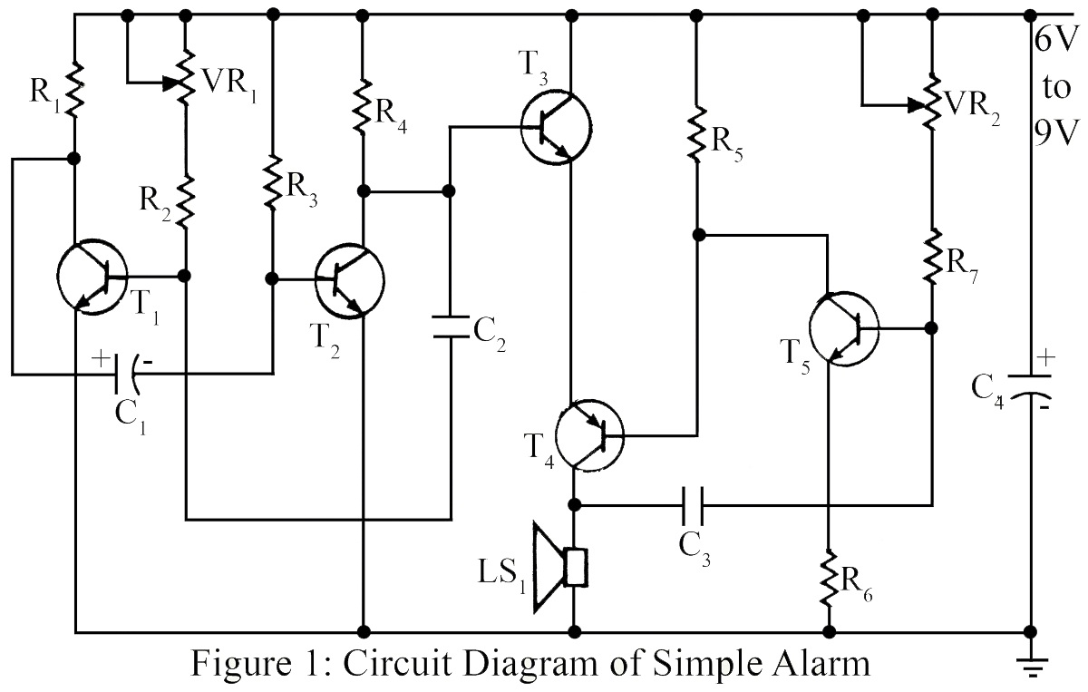
The simple circuit generates an audible alarm notification, functioning as a burglar alarm utilizing five transistors. This circuit operates as a basic burglar alarm system designed to emit an audible sound when triggered. The core component of the circuit is...
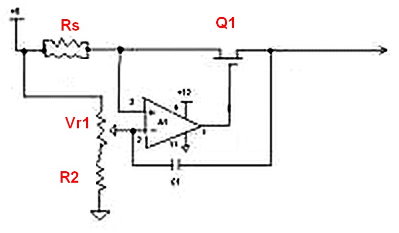
Assuming a 5V output can be achieved after adjusting the potentiometer, will the 240-ohm resistor limit the current, or is there a need to add additional components? If it does limit the current, it is expected that the power...
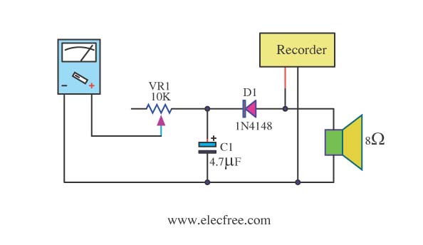
Expensive stereo systems generally feature VU meters that help indicate maximum power levels to prevent overloading. However, typical radio tape players do not include VU meters. A potential solution involves using a multimeter as a replacement. This can be...
The Flip-Flop Robot drives forward until it encounters an obstacle, at which point it reverses until it strikes another obstacle. This back-and-forth motion continues indefinitely. By simplifying the functionality to this basic behavior, the robot can be constructed using...