
Police bicycle siren circuits

The sound generator circuit employs an op-amp configuration to produce a variable frequency output, which is essential for generating the siren effect. The operational amplifier IC1 is configured in a feedback loop with capacitors and resistors that determine the frequency and amplitude of the output signal. The diodes D1 and D2 serve to shape the waveform, ensuring that the output maintains a specific form conducive to alarm applications.
The charging and discharging of capacitor C3 is a critical aspect of this circuit. When switch S1 is pressed, C3 begins to charge, storing energy that is later released to create the sound pulse. The resistor R7 plays a vital role in controlling the current flow to the op-amp, preventing overload and ensuring stable operation of the circuit. The detector circuit formed by resistors R1 and R2 is responsible for monitoring the output signal levels and providing feedback to maintain the desired operational characteristics.
Transistor Q1 (BC639) acts as a power amplifier, allowing the circuit to drive the loudspeaker SP1 effectively. The biasing of Q1 is crucial, as it determines the transistor's operating state. When Q1 is biased into the active region, it allows for significant current flow through SP1, resulting in the loud siren sound that is characteristic of alarm systems.
Overall, this sound generator circuit is a robust solution for alarm applications, utilizing fundamental electronic components to create a reliable and effective warning signal. Its design ensures that it can be easily integrated into various alarm systems while providing clear and audible alerts.This circuit is the sound generator super siren, for use be alarm signal get by live frequency generator circuit that use, op-amp circuit. The principle works to are while still no press switch S1 will still have no the loud sound comes out from a loudspeaker SP1.
When do pressure switch S1 then liberate C3 do something charge full until while press switch S1 and discharge go out. When liberate switch S1 come in at R7. Which perform in something limit current come in at 3 Non inverting legs of IC1a. By IC1, D1, D2, C1, C2 and R5 build be sound generator signal circuit then export come to way pin 6 of IC1a come to reach at pin 3 (Noninverting) of IC1b. By have R1 and R2 build be Dectector circuit. For do fining level has signal then signal to come out the way pin 7 of IC1b which will have flowing through comes in at pin B of Q1 for do something bias give Q1(BC639) bias.
When Q1(BC639) work then make SP1 make a noise loud come out and make a noise poor loud C3 discharge be finished SP1 then stop make a noise loud. 🔗 External reference
Related Circuits
The following circuit illustrates the electronic diagram design for police and ambulance alarms. Features include simplicity and ease of assembly, as well as cost-effectiveness. This electronic schematic represents a basic alarm system intended for use in police and ambulance applications....
IC2 is configured as a low-frequency astable multivibrator with a cycle period of approximately 6 seconds. The gradually varying ramp waveform generated at capacitor C1 is fed into the emitter follower transistor Q1, which subsequently frequency modulates the alarm...
The IRF820 MOSFET has a voltage rating of 500V; it should work well in preamp stages of most tube amps. The 100-ohm resistor is there to suppress H.F. oscillations. If the IRF820 is physically close to the 12AX7 plate,...
This simple circuit can be used to charge a pair of AA or AAA-sized cells using solar energy. It has been utilized to maintain the operation of devices such as a Palm Pilot and a Walkman radio continuously. This...
The circuit includes a momentary switch S1 that triggers an alarm pulse for the decade counter IC2, which increments its count with each alternating alarm pulse or the activation of switch S1. Ten variable resistors (VR1 through VR10) are...
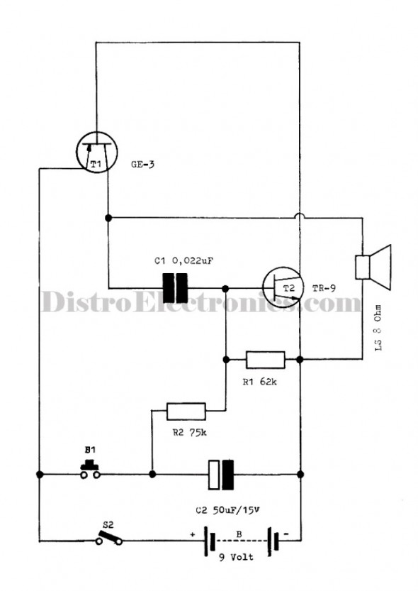
Siren Circuit. This circuit generates a sound siren when switch S1 is pressed, increasing the sound frequency as capacitor C1 charges. The sound frequency decreases when switch S1 is released. The siren circuit operates based on the charging and discharging...