
Simple Diode Curve Tracer
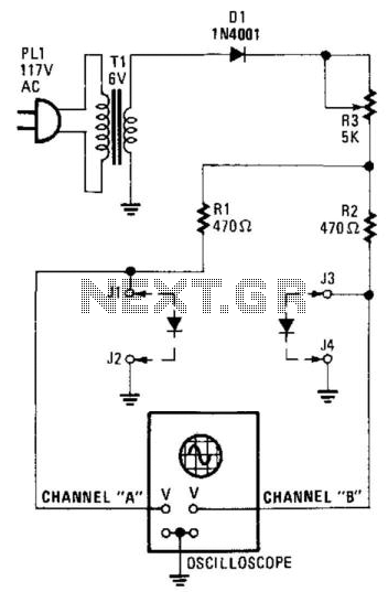
The circuit in question serves as a versatile tool for analyzing the voltage-current (VI) characteristics of two-terminal devices, primarily diodes. The fundamental operation involves applying a varying voltage across the device under test, allowing for the observation of current flow and the corresponding voltage drop. This is essential for understanding the behavior of diodes under different conditions, including forward and reverse bias.
To implement this circuit, a transformer is typically employed to step up the input voltage to the desired level. The transformer must be selected based on the maximum voltage requirements of the devices being tested. Additionally, the resistors R1 and R2 play a critical role in setting the current limits and ensuring safe operation. By increasing the values of these resistors, the circuit can accommodate devices with higher current ratings without risking damage to the components or the device under test.
The circuit can be further enhanced by incorporating measurement devices such as ammeters and voltmeters, which can provide real-time readings of current and voltage, respectively. This allows for precise plotting of the VI characteristics on a graph, facilitating a deeper analysis of the diode's performance.
Furthermore, additional features such as variable resistors or potentiometers can be integrated into the circuit to allow for fine-tuning of the test conditions. This adaptability makes the circuit suitable for a wide range of laboratory applications, from educational demonstrations to advanced research in semiconductor behavior.
In summary, this circuit is an essential tool for electronics laboratories, providing a reliable method for evaluating the characteristics of diodes and similar two-terminal devices through adjustable voltage and current settings. Suitable for matching diodes or examining VII characteristics of two terminal devices (diodes, etc.), this circui t should be handy for lab use. Ri and R2 can be increased in value and a higher voltage transformer can be used for higher voltage test using this principle. 🔗 External reference
Related Circuits
VOX is a voice-controlled switch commonly used for microphones, serving as a replacement for the traditional switching button. The actuating threshold is adjusted through the volume potentiometer. The VOX (Voice Operated Switch) circuit functions by detecting sound levels and activating...
This circuit diagram represents a simple yet effective transmitter circuit, capable of transmitting telephone conversations. When the telephone receiver is on the hook, the line voltage is approximately 48 volts. The R7 preset resistor is adjusted to achieve a...
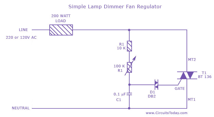
A fan regulator circuit that can also function as a simple lamp dimmer circuit. This fan speed regulator or light dimmer operates based on power control using a triac. The fan regulator circuit is designed to control the speed of...
Simple Surround Sound Decoder. Introduction This surround-sound decoder is based on the Hafler principle, first discovered by David Hafler sometime in the early 1970s. The original idea. The simple surround sound decoder utilizes the Hafler principle to create an immersive...
In the event of a sudden power failure in an elevator, it is crucial for the duty officer in the distribution room to be alerted promptly to prevent panic among passengers trapped inside. The following describes a sound alarm...
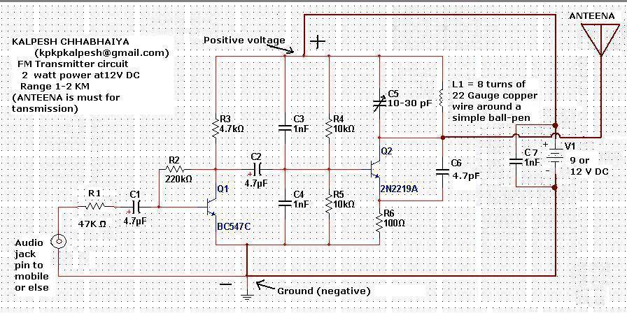
Constructing an FM transmitter for the first time can be challenging due to confusion regarding the necessary components, parts, design, PCB layout, and transmission aspects. An FM transmitter is an electronic device that encodes audio signals into radio frequency waves,...
Warning: include(partials/cookie-banner.php): Failed to open stream: Permission denied in /var/www/html/nextgr/view-circuit.php on line 713
Warning: include(): Failed opening 'partials/cookie-banner.php' for inclusion (include_path='.:/usr/share/php') in /var/www/html/nextgr/view-circuit.php on line 713