
FOLDBACK CURRENT LIMITER

The circuit operates by utilizing two transistors, Q1 and Q2, to manage the current flow and protect against overload conditions. Q1 is configured as a current-sensing device that monitors the load current. Under normal operating conditions, Q1 remains in saturation, allowing current to flow freely to the load. However, when the load current exceeds a predetermined threshold, the base current of Q1 decreases, leading to a reduction in collector current. This causes a voltage drop across the unmarked resistor, which can be calculated based on the desired saturation point of Q1.
When a short circuit occurs, the current through the load rises dramatically, triggering Q2 to turn off. This action effectively disconnects the load from the power supply, preventing damage to both the load and the power supply. The feedback mechanism provided by Q2 ensures that the short-circuit current is limited to a safe level, thus enhancing the reliability of the circuit.
To implement this circuit successfully, careful selection of the unmarked resistor value is crucial. It should be chosen based on the maximum load current that the circuit is designed to handle, ensuring that Q1 remains in saturation during normal operation. The design should also consider the power ratings of the components used to prevent overheating and ensure long-term reliability. Overall, this circuit design provides a robust solution for protecting electrical loads in various applications.Provides overload and short-circuit protection for load while isolating malfunctioning circuit from other loads on common supply bus. In normal operation, Q1 is saturated. When load attempts to draw more than this saturation value, base current of Q1 cannot maintain saturation so voltage across unmarked resistor drops and current through Q1 drops
correspondingly. When load is shorted, Q2 goes off and short-circuit current folds back to safe lower value. Choose value of unmarked resistor to ensure saturation of Q1 at load current. -S. T. Venkataramanan, Simple Circuit Isolates Defective Loads, EDN Magazine, Jan. 20, 1978, p 114. 🔗 External reference
Related Circuits
This project was begun as a means to charge and cycle NiCad batteries but has become a versatile tool for experiments requiring either a controlled voltage up to +30V and/or a current of +/- 2.5 Amps. If all you...
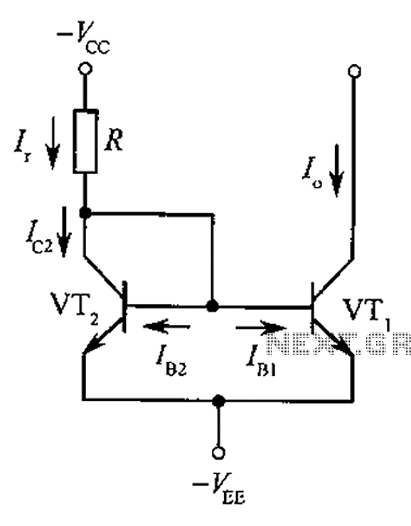
The circuit depicted is a mirror substantially constant current source circuit, in which transistors VT1 and VT2 are matched to each other. The figure illustrates that the current through Ir is equal to Ic2 plus the sum of base...
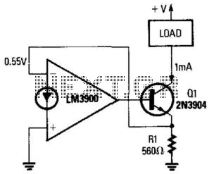
A fixed current flows through any load that is connected between the positive supply and Q1's collector. The non-inverting terminal of the operational amplifier is grounded, and negative feedback flows between the output of the circuit (Q1's emitter) and...
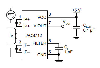
The primary component utilized is the ACS712 sensor from Allegro MicroSystems, designed for measuring current. It offers cost-effective and accurate solutions for AC or DC current sensing in industrial, commercial, and communication systems. A precise, low-offset, linear Hall sensor...
This is a high quality power supply with a continuously variable stabilised output adjustable at any value between 0 and 30VDC. The circuit also incorporates an electronic output current limiter that effectively controls the output current from a few...
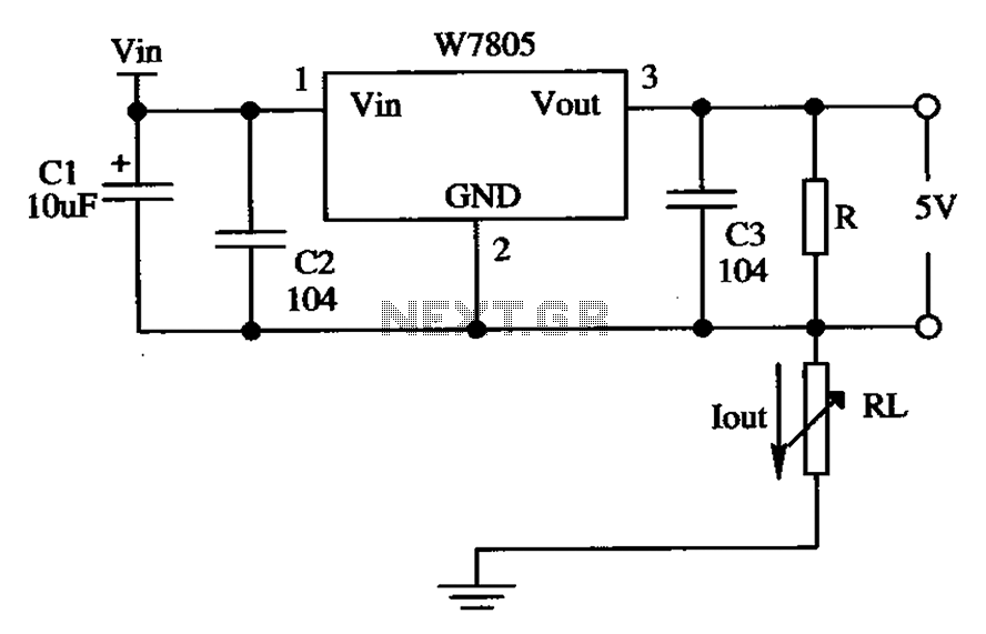
The circuit is composed of a W7805 positive current source application integration circuit that includes a voltage regulator. The W7805 regulator operates in suspension. A resistor is placed between its output terminal and the common terminal, forming a constant...