
Inexpensive Isolation Transformer (Impromptu Setup) Circuit
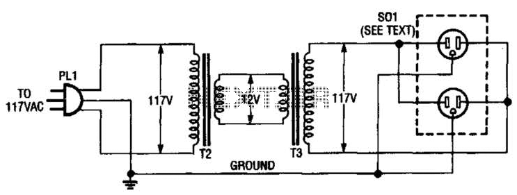
To construct the described isolation transformer, the two 12-V transformers should be connected in such a way that the primary winding of one transformer is connected to the secondary winding of the other. This configuration allows for electrical isolation between the input and output, which is crucial for safety when testing or servicing electrical devices. The transformers should be rated for at least 50 W to ensure they can handle the load without overheating.
The use of a duplex AC receptacle enables the connection of standard electrical devices for testing purposes. It is essential to ensure that the transformers are properly rated for the intended voltage and current levels. Heavy-gauge wire must be used for the interconnections between the 12-V windings to minimize voltage drop and heat generation due to high current flow.
In terms of safety, it is advisable to incorporate fuses or circuit breakers in the circuit to protect against overload conditions. Additionally, proper insulation and secure mounting of the transformers will help prevent accidental contact with live parts, enhancing the safety of the testing setup. Proper grounding of the transformer chassis and receptacle is also recommended to prevent electric shock hazards.
This isolation transformer setup is particularly useful for servicing low-power devices, as it provides a safe testing environment while ensuring that the equipment under test is isolated from the mains supply. Using two 12-V filament or power transformers, an impromptu isolation transformer can be made for low-power (under 50 W) use in testing or servicing. SOI is an ordinary, duplex ac recept-able. Use heavy-wire connections between the 12-V windings because several amperes can flow. 🔗 External reference
Related Circuits
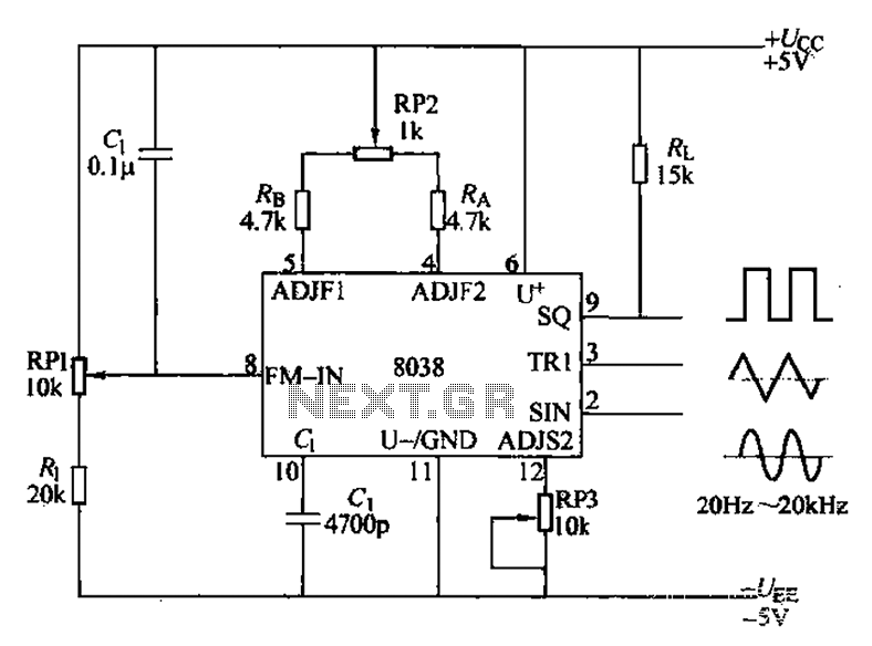
The audio function generator integrated circuit ICL8038 is capable of producing square waves, triangle waves, and sine waves. The electrical resistance and potentiometer RP1 are utilized to determine the 8-pin DC potential Ua, which is typically set to 2Ucr/3....
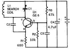
This metal detector circuit needs to be powered using a 9 volts power supply (DC) or a 9 volts battery. The C1 capacitor is a variable capacitor with a value of 365 pF, C2 is a 100 pF silver...
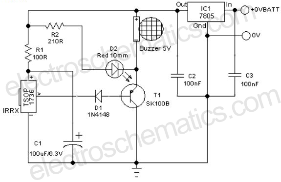
A remote-controlled alarm circuit utilizing the TSOP1736 is designed for easy use by elderly individuals or patients confined to bed. This battery-operated alarm system eliminates the need for routing electric cables to a calling bell switch, making it a...
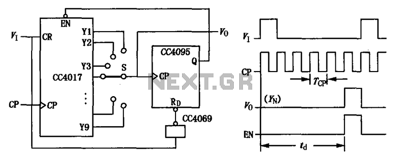
CC4017 counter/distributor featuring a circuit diagram of the delay. The CC4017 is a decade counter and distributor that counts from 0 to 10, providing ten output states. It is commonly used in various digital applications for counting purposes, such as...
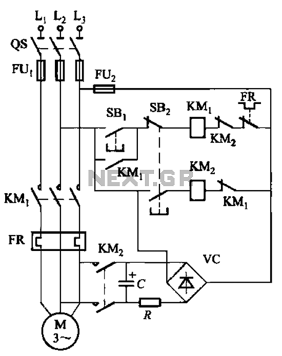
The circuit depicted in Figure 3-138 utilizes the principle of energy storage through capacitor discharge to achieve braking. The capacitance (C) and resistance (R) parameters are determined based on the size of the motor power. The capacitance (C) is...
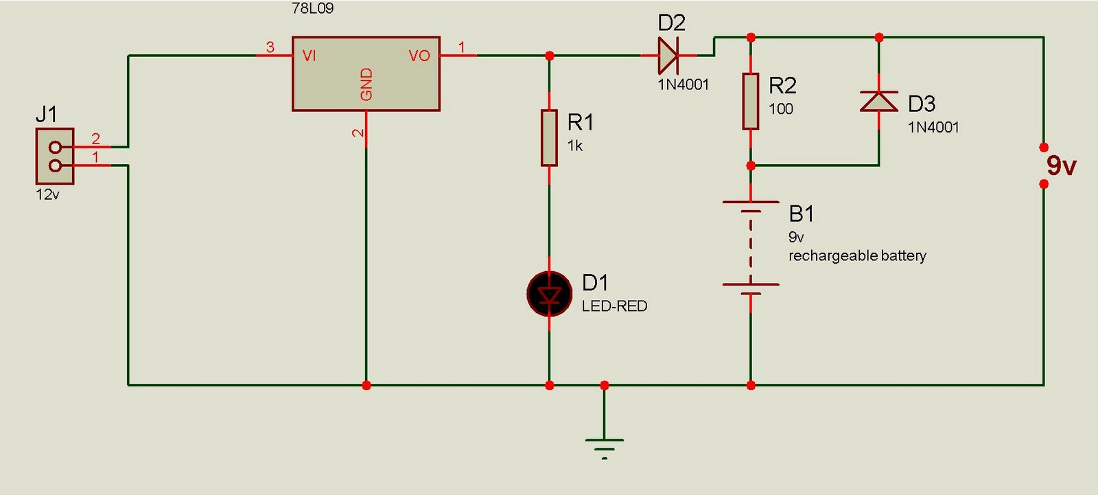
This battery backup circuit can be integrated into surveillance systems or alarm controls to provide power during mains power failures. The battery backup will immediately take over the load without any delay, and the circuit is simple to construct....