
The simplest digital LCD voltmeter with AVR
The digital voltmeter circuit is designed to provide a straightforward solution for measuring voltage levels across various applications. It employs an Atmel AVR microcontroller, which serves as the core processing unit. The selected microcontrollers (ATmega16A, ATmega16L, ATmega16, ATmega32A, or ATmega32) are well-suited for this application due to their integrated ADC capabilities and low power consumption.
The LCD display, specifically the LCD3 type, is integral for visual feedback, allowing users to easily read voltage values. The driving mechanism of the display relies on a 50Hz rectangular AC voltage, ensuring that the active segments illuminate correctly in relation to the common electrode. This design choice not only simplifies the circuit but also enhances the display's visibility.
The ADC operates within a defined range, translating the analog voltage inputs into digital values that the microcontroller can process. The decision to limit the output range to 0-999 is practical, as it aligns with the display capabilities and the expected input voltage levels. The input voltage divider formed by R9, R10, and P1 is critical for scaling down higher voltages to a manageable level for the ADC, allowing for precise measurements while maintaining a high input impedance.
Calibration is a vital step in ensuring measurement accuracy. The use of a potentiometer (P1) allows for fine-tuning, accommodating variations in input voltage. The option to select the decimal point enhances the user interface, providing flexibility based on user preferences.
Power consumption is kept low, making this voltmeter suitable for battery-operated applications. The recommended power supply components (7805, LM317, or Zener diode) facilitate easy integration into existing systems, while the inclusion of a fuse adds a layer of protection against overcurrent scenarios.
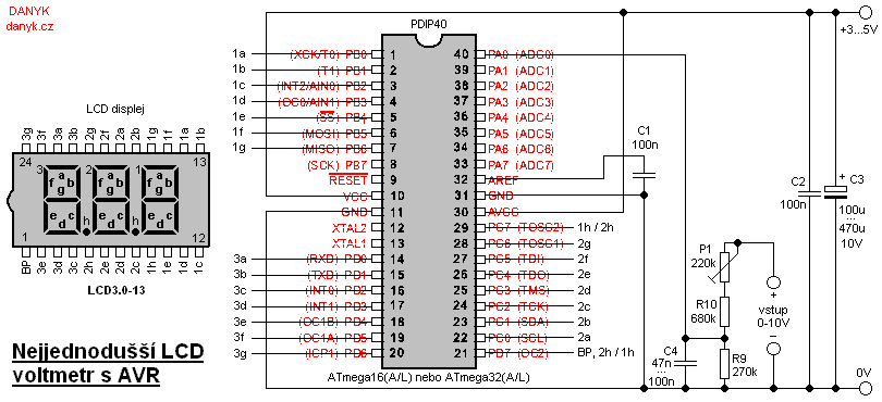
Overall, this digital voltmeter circuit represents an efficient and effective solution for voltage measurement, suitable for a variety of applications ranging from laboratory setups to automotive diagnostics.This is probably the simplest possible digital voltmeter with Atmel AVR microcontroller and LCD display. The circuit is controlled by a microprocessor IO1 - AVR Atmel ATmega16A, ATmega16L, ATmega16, ATmega32A, ATmega32L or ATmega32.
Below is a program to download for free and configuration bits setting printscreen. The three digit seven segment LC D display is used to display the voltage value. I used the LCD3. 0-13 type. The display is driven by a rectangular AC voltage at a frequency of about 50Hz. Active segments are connected to a voltage in-phase with a common electrode or so called backplane (BP). Inactive segments are connected to a voltage in phase with the common electrode. The circuit uses single ended 10-bit AD converter of the AVR. The output value is in range of 0 to 1023. As is not worth adding a fourth digit for the narrow range of 1000 - 1023, the range is limited to 0 - 999.
When the input voltage is out of range, the display shows a symbol "- - -". The scale corresponds to an input voltage of 2. 5 V. The input divider of R9, R10 and P1 decreases the voltage by 4, providing a 10V range with a resolution of 0. 01 V. The input impedance is about 1M. (If you require a 100V range, replace R10 to 9M1 and P1 2M2. Then you`ll get 100V range with a resolution of 0. 1 V and an input impedance of around 10M. ) Calibrate the voltmeter using P1 while a known voltage is connected. Select the decimal point as needed (1h or 2h). The selected point connect to pin 29 (PC7). Unused point should be connected to pin 21 (PD7) and thus to BP, so there`s no voltage respect to BP (do not let the point "in free air").
Refresh rate of the voltmeter is about 4Hz. IO1 uses an internal RC oscillator set to 1MHz. The circuit is powered from a supply of about 3 - 5V for ATmega16A / ATmega32A / ATmega16L / ATmega32L or 4. 5 - 5V for ATmega16 / ATmega32 (according to my experiments ATmega32 operates at 3V too, but it is not guaranteed by the datasheet).
Current consumption at 3V is about 0. 2 to 0. 4 mA and at 5V it is about 2-4 mA. The voltmeter can be useful as an improvement for a lab power supply, vehicle board voltage indicator, the PC power supply voltage meter, UPS battery voltage meter, etc. The supply voltage can be obtained using a simple power supply using for exampe the 7805, LM317 or a zener diode.
Put the proper fuse at the power input. 🔗 External reference
Related Circuits
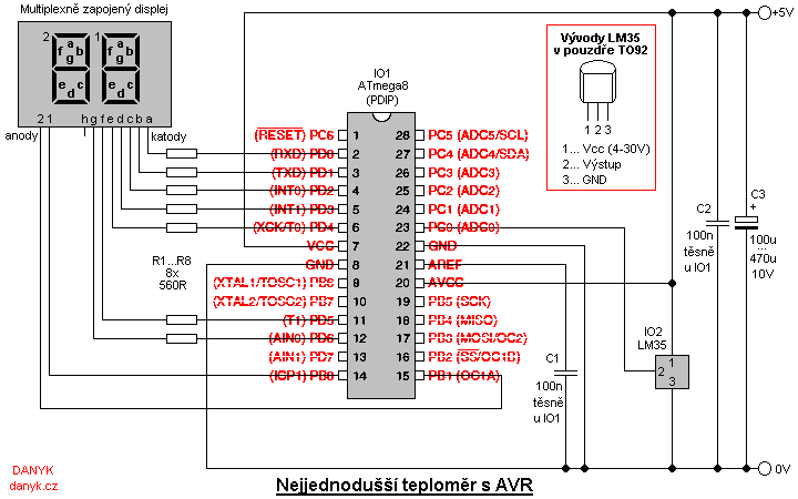
This is a simple digital thermometer utilizing an Atmel AVR microprocessor, capable of measuring temperatures in the range of 2 to 99 °C with a resolution of 1 °C. The circuit is managed by an Atmel AVR ATmega8, ATmega8L,...
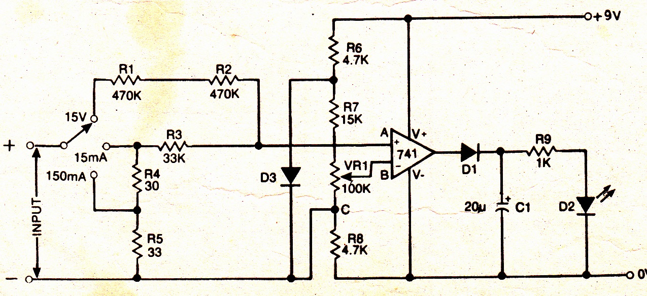
A simple electronic multimeter offers an affordable alternative for hobbyists deterred by the high cost of conventional multimeters. This device is designed to measure three ranges: (i) 0-15V, (ii) 0-15mA, and (iii) 0-150mA, with the possibility of extending the...
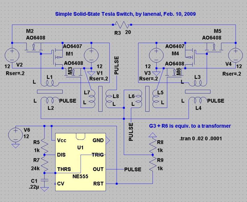
This circuit is designed for ease of tuning. When the pulse voltage reaches 6V, all transistors operate as open switches, eliminating the risk of battery shorts. The pulse voltage source V5 can be substituted with a 555 astable circuit....
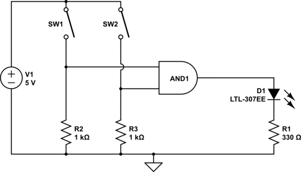
The AND output will be high when both switches are closed. However, there is no assurance regarding the input levels when the switches are open, resulting in unpredictable outcomes. In an electronic circuit utilizing an AND gate, the operation is...

The Kelvin scale version reads from 0 to 1999 K theoretically, and from 223 K to 473 K actually. The 26 kΩ resistor brings the input within the ICL7106 common-mode voltage range; two general-purpose silicon diodes or an LED...
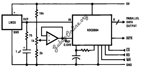
This is a design for a temperature-to-digital converter circuit that is controlled by the LM35 integrated circuit. The LM35 is a precision integrated circuit temperature sensor, whose output voltage is linearly proportional to the Celsius temperature. The circuit utilizes the...