
Simple Analog to Digital Converter
The construction of a basic Analog to Digital Converter (ADC) utilizes operational amplifiers configured as comparators to achieve the conversion of an analog input voltage into a digital binary output. The ADC operates by comparing the input voltage against a reference voltage set at Vcc/2. This configuration allows for the effective determination of the binary output based on the relative magnitude of the input voltage.
The inverter-comparators, designated A1 through A4, are critical components in this circuit. They are designed to switch states when the input voltage reaches the midpoint of the power supply voltage, ensuring accurate conversion. The error tolerance of Vcc/(2n-2) is crucial for maintaining precision in the output binary code, where 'n' represents the number of bits in the output. The design ensures that the output from the comparators is sufficiently close to the supply voltage levels, facilitating reliable digital representation.
Operational amplifiers chosen for this application must possess high input impedance to minimize the loading effect on the input signal and low output impedance to drive subsequent stages effectively. The configuration of the inverting inputs to Vcc/2 is essential for the comparators to function correctly, as it establishes the reference level for comparison.
For applications requiring lower resolution, specifically up to four bits, the use of quad CMOS logic elements such as NAND or NOR gates can simplify the design while maintaining functionality. This adaptation not only reduces component count but also enhances the overall efficiency of the circuit.
The input impedance of approximately 22 kilohms ensures compatibility with various signal sources, while the conversion time of less than 300 ns indicates the circuit's capability for rapid response, making it suitable for applications where speed is critical. Overall, this ADC design exemplifies a straightforward yet effective approach to analog-to-digital conversion, leveraging commonly available components to achieve desired performance metrics.The simplest Analog to Digital Converter (ADC) can be constructed as shown in Figure 1. Input voltage which can range from zero up to power supply voltage (Vcc) converts to parallel additional binary code at the outputs of the converter. For normal operation of the ADC requires that the inverter-comparators A1-A4 should be able to switch when the
voltage on their inputs equal to Vcc/2 and an error must be no more than Vcc/(2n-2) (n - number of bits of binary code at output), and the output voltage of the comparator in on/off states should be close to zero and to the Vcc. In addition, the comparator must have a high input and low output impedance. Most of the modern op amps is satisfied for these requirements, the inverting inputs of this op amps should be connected to the Vcc/2 (half of power supply voltage).
If the required accuracy of analog to digital conversion does not exceed four bits, then as the basis for the ADC can be used quad CMOS logic elements "NAND" or "NOR". One of the possible approaches to construct this device is shown in Figure 2. The input impedance of this circuit is about 22 kilohms, and the time of conversion - less than 300 ns.
🔗 External reference
Related Circuits
This project is considered intermediate to advanced and is not recommended as a first project for individuals who are new to synthesizers or electronics. The circuit and some explanations are provided, assuming that the builder has significant experience in...
When it is necessary to transmit a digital signal between two electrically isolated circuits, an optoisolator or transformer coupling is typically employed. However, both solutions have limitations; optocouplers are effective only up to approximately 10 MHz, while transformers exhibit...
This circuit is a simple buzzer circuit known as a novel buzzer. It utilizes a relay in series with a small audio transformer and a speaker. The relay will activate the circuit. The novel buzzer circuit operates by employing a...
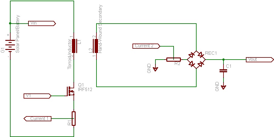
This document discusses the future direction of the Free Charge Controller project and proposes a new solar charge controller circuit. The Free Charge Controller project aims to enhance the efficiency and effectiveness of solar energy management systems. The proposed solar...
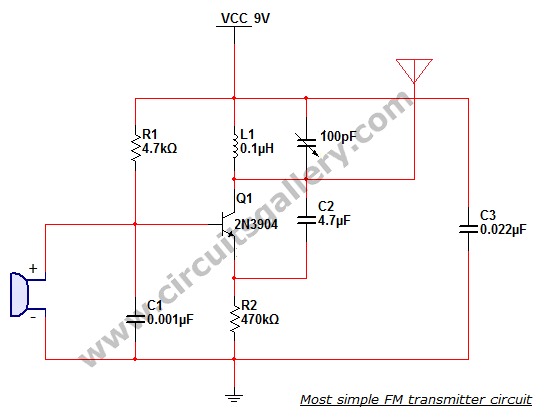
This is the simplest single transistor FM wireless transmitter circuit ever posted in CircuitsGallery. In the field of telecommunications, frequency modulation (FM) transmits information by altering the frequency of a carrier wave based on the message signal. FM utilizes...
This circuit is designed to drive a total of 42 LEDs, assuming a forward voltage of approximately 2.2V per LED and a forward current of around 21mA for adequate brightness. If the specifications of the LEDs differ significantly, modifications...
Warning: include(partials/cookie-banner.php): Failed to open stream: Permission denied in /var/www/html/nextgr/view-circuit.php on line 713
Warning: include(): Failed opening 'partials/cookie-banner.php' for inclusion (include_path='.:/usr/share/php') in /var/www/html/nextgr/view-circuit.php on line 713