
Simple Temperature Indicator
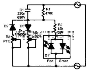
The circuit design utilizes a two-color LED (D1) to provide a visual indication of temperature changes. The NTC and PTC resistors (R4 and R3) are critical components that respond to temperature variations. The NTC resistor decreases in resistance as temperature increases, while the PTC resistor increases in resistance under the same conditions. This complementary behavior allows for a gradual transition in the LED's color from green to red, effectively communicating the thermal status of the equipment.
The LED indicator is powered directly from the mains supply, which necessitates careful design considerations to ensure safety and reliability. The circuit employs a diode (D2) in conjunction with R3 to rectify the AC mains voltage, allowing for appropriate biasing of the LED. The resistor R2 plays a vital role in current limiting, preventing excessive current flow that could damage the LED or other components.
Capacitor C1 serves to stabilize the voltage across the LED, smoothing out fluctuations that may occur due to mains voltage variations. The choice of component values for R3 and R4 is essential for achieving the desired temperature sensitivity and response time. The recommended dimensions for these resistors ensure they can handle the thermal load without failure.
Overall, this circuit is designed for applications where monitoring temperature is critical, and an intuitive visual alert system is required. It combines effective temperature sensing with a straightforward LED indication, making it suitable for various environments where overheating could pose a risk. Proper assembly and adherence to safety standards are imperative, given the direct connection to mains voltage. For the absolute measurement of temperatures, a thermometer is indispensable. However, in many situations, an absolute value is not needed and a relative indication is sufficient. It would be a further advantage if a green light would indicate that all is well as far as temperature is concerned. As the temperature rises, the light should change color slowly to indicate that the equipment is getting too hot.
This circuit does this and works directly from the mains. The indicator proper is a two-color LED (Dl), while the sensor is a combination of a negative-tempeniture coefficient (NTC) and a positive-temperature coefficient (PTC) resistor (R4 and R3, respectively). At a relatively low temperature, the value of R3 is low and that of i4 is high. During the positive half cycle of the mains voltage, a voltage will exist across R3/D2 that is sufficiently high to cause the green section of Dl to light.
The value of i3 has been chosen to ensure that during the negative half cycle of the mains voltage, the potential across it is too low to cause the red section of Dl to light. If the temperature rises, the value of i4 diminishes and that of i3 rises. Slowly, but surely, the green section will light with lesser and lesser brightness. At the same time, the red section lights with greater and greater brightness until ultimately only the red section will light.
Resistor R2 and capacitor CI ensure that the current drawn by the LEDs does not become too large. This arrangement keeps the dissipation relatively low. Both R3 and R4 should be of reasonable dimensions—approximately 6 mm in diameter, not less. At 25°C, the NTC must be 22 to 25 kfl and the PTC must be 25 to 33 . The circuit should be treated with great care because it carries the full mains voltage. 🔗 External reference
Related Circuits

The experimenter's pot is a solid state potentiometer using Dallas semiconductor's DS1869 and National's LM78L05, two electrolytic capacitors, two small push button switches, and two optional Molex connectors. This project is very useful, especially in finding the right value...
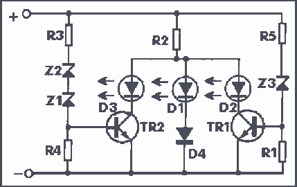
The operating principle of the circuit is very simple. The first LED D1 is placed in series with the resistor R2 and diode D4. An only be lit this LED indicates that the battery is overcharged. For this reason,...

This is a simple-to-build PIC temperature meter that allows for simultaneous temperature measurement in two different locations. Such a useful and powerful circuit can be constructed with minimal components while offering extensive possibilities. This is made feasible by utilizing...

The Door Buzzer circuit utilizes an IC 555 to generate a sound resembling an electric bell. When the switch S1 is pressed, a loud sound is produced. This circuit is designed to be simple and requires minimal components. It...
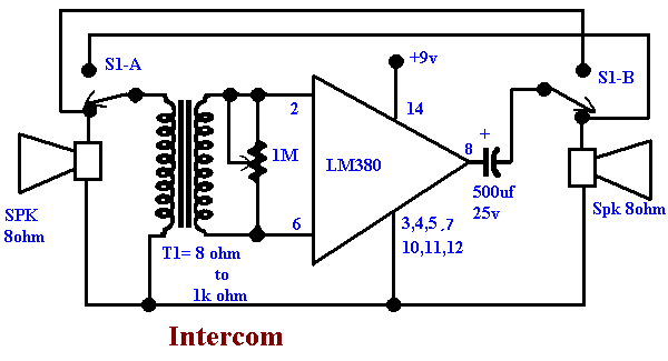
This circuit was requested by a school teacher. It is a simple intercom that anyone can assemble and operate. It is based on the LM380 integrated circuit (IC). The intercom circuit utilizing the LM380 IC is designed for straightforward assembly...

LED stereo sound level indicator for audio amplifier. Many circuits can be designed as level indicators by using a comparator IC or transistors, but... The LED stereo sound level indicator serves as a visual representation of the audio signal levels...