
simple thyristor circuits explained

No description available.
Related Circuits
The project "DIY: Build a Sound Activated Switch" presented here is straightforward to construct and can be very useful in protecting a specific area from potential theft or intrusion. Learn how to build a simple sound-activated alarm here on...

This topic will be locked and will display all of the circuits and some photos of the devices being worked on in the Joule Thief topic. This process will take some time, so patience is appreciated. If any errors...
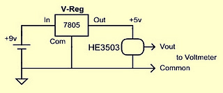
The above pictured schematic diagram is just a standard constant current model with a added current limiter, consisting of Q1, R1, and R4. The moment too much current is flowing biases Q1 and drops the output voltage. The output...
Remove the 6 mm screw that secures the lower rear fairing cover. This cover is the black plastic piece to which the spark plug protectors are attached. Only the machine screw should be removed; do not detach the lower...

The inverting input is maintained at a low level via a 10K resistor when the circuit is powered on but not in use. During measurement activities, including calibration measurements where the input is floating, this resistor is disconnected. The...
It was observed that balls were becoming lodged in the ball trough, failing to load into an upkicker or not resting correctly on the trough ball microswitches or optos, which caused the machine to register a missing ball. Initially,...