
Simple Transistor Reflex Receivers
This reflex radio circuit utilizes a minimalist approach to achieve functionality, drawing inspiration from classic two-transistor designs. The circuit is built around two transistors that serve as amplifiers, with the first transistor receiving the radio frequency (RF) signal and the second transistor functioning as a driver for the audio output. The inter-stage transformer plays a crucial role in coupling the output of the first transistor to the input of the second, thereby eliminating the need for additional amplification stages.
The antenna coil consists of 20 turns of wire, wound around four insulated posts. This configuration is designed to maximize the effective length of the antenna while maintaining a compact form factor. The choice of materials for the posts, such as nylon or insulated bolts, ensures that there is no unintended grounding or signal loss, which is vital for maintaining signal integrity in RF applications. The dimensions of the coil are flexible, allowing for some customization based on the enclosure used for the radio.
Signal coupling is accomplished using a secondary winding of two turns, which is placed directly atop the main 20-turn winding. While this method simplifies the construction of the circuit, it introduces additional capacitive coupling. This capacitance can adversely affect the tuning range of the circuit, particularly when utilizing a standard 365 pF variable capacitor, which is commonly used in radio frequency tuning applications. Careful consideration must be given to the layout and winding technique to mitigate these effects and optimize performance.
Overall, this reflex radio project exemplifies a blend of simplicity and functionality, drawing from historical designs while incorporating modern insights into RF circuit design. The result is a compact and effective radio capable of receiving a variety of signals with minimal components.This reflex radio project was inspired by Robert Bazian 's design. His reflex radio is the "darndest" thing I have seen and his spectacular results inspired me to come up with my own version! These designs are similar to two-transistor circuits used in some ancient Japanese "Boys Radios" except that the inter-stage transformer directly drives the speaker.
The antenna coil is just 20 turns wrapped around four insulated posts as seen in the photos and shown in the diagram below. I used nylon posts but ordinary bolts covered with tubing would work fine. The dimensions are not particularly critical; those shown happen to fit inside the case I chose. The signal is coupled to the receiver by two turns wrapped right on top of the 20 turns. This winding technique is simple but it has the drawback of having more than desirable capacitance and that limits the tuning range with a standard 365 pF variable ca 🔗 External reference
Related Circuits
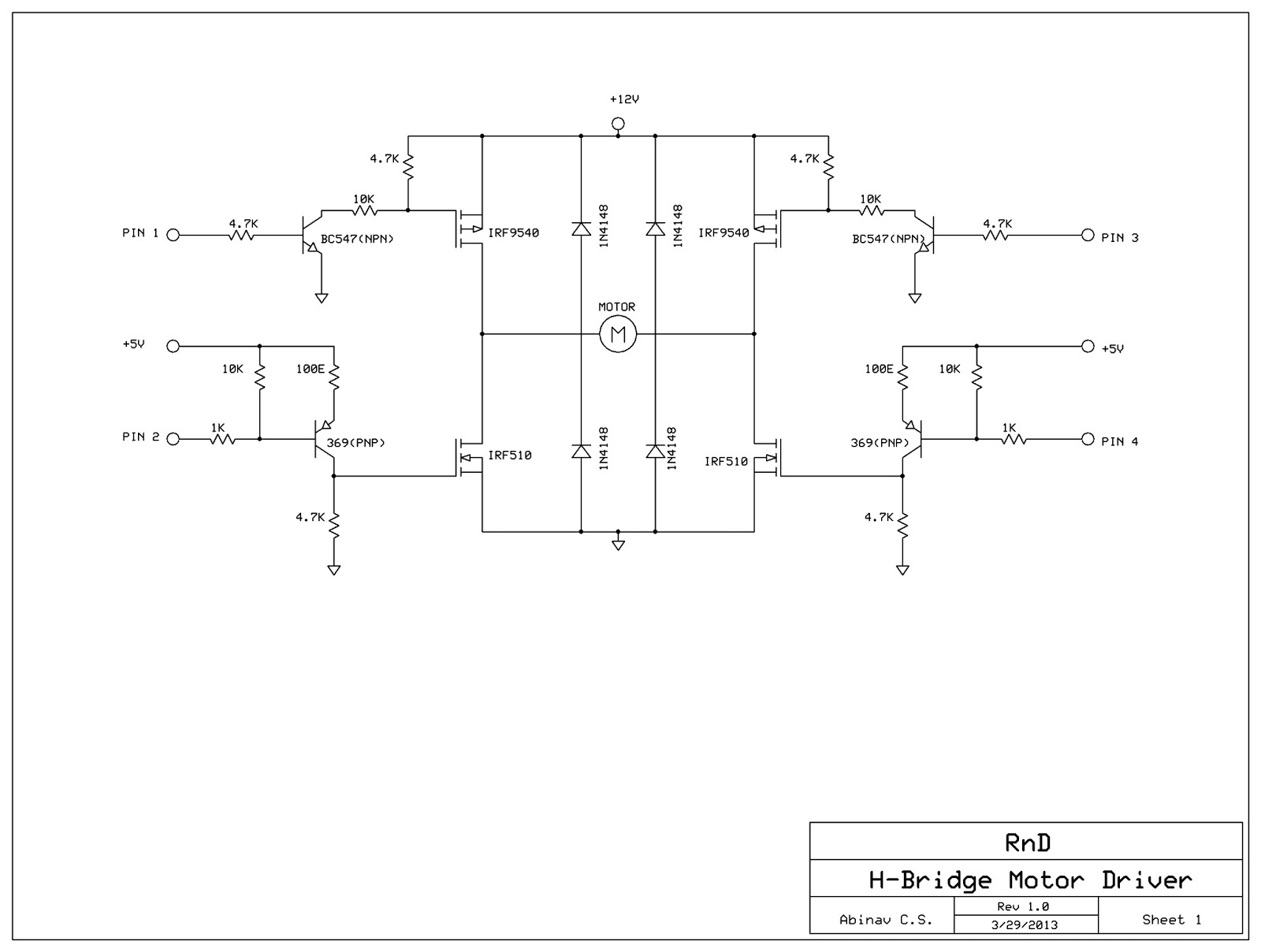
This post discusses the construction of an H-Bridge Motor Driver circuit using simple MOSFETs and transistors. The primary feature of this H-Bridge is its ability to drive a motor in both directions. An H-Bridge is a circuit that allows...
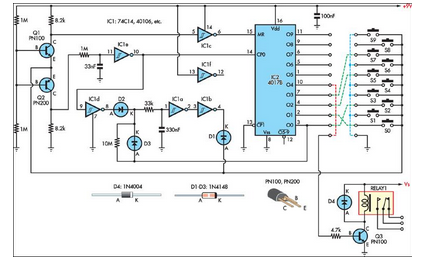
This simple combination lock accommodates codes ranging from 1 to 9 digits in length, with the only restriction being that the same digit cannot be used twice. The circuit... A combination lock circuit can be designed using a microcontroller or...
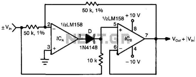
When the input voltage is positive, the output of ICA is negative, resulting in diode D not conducting; therefore, the output of ICB is positive. Conversely, when the input is negative, the output of ICA becomes positive. Diode D...
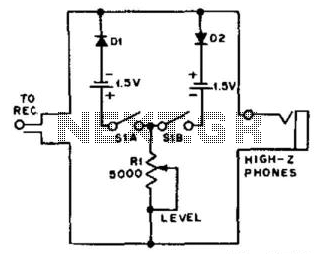
For use with headphones, this circuit sets the audio clipping level via a 5-kOhm potentiometer. This type of noise clipper is most effective for pulse-type noise with a low duty cycle, such as ignition noise. The resistor Rl establishes...
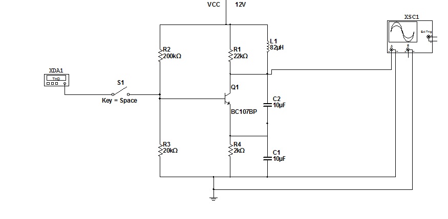
To simulate this circuit, NI Multisim produced by National Instruments is required. The oscillator will generate a stable waveform. If a file needs to be saved, navigate to the source code. It is important to use Multisim version 11....
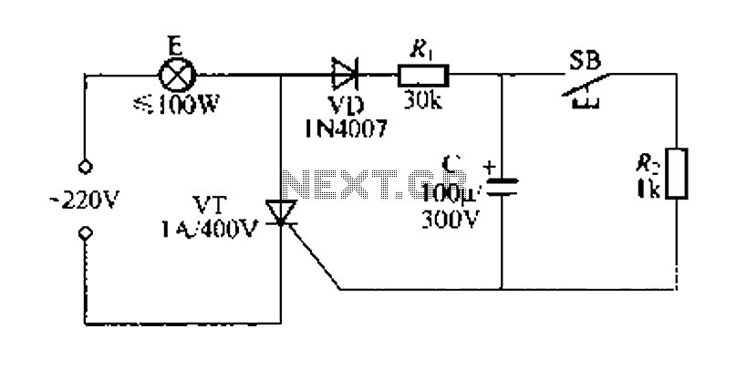
Figure 57 illustrates a simple delay lamp circuit that connects to lamp E using a two-wire connection. This design allows for the security bars to be installed directly, enabling replacement with a standard wall switch without altering the existing...