
Temperature-compensated crystal oscillator
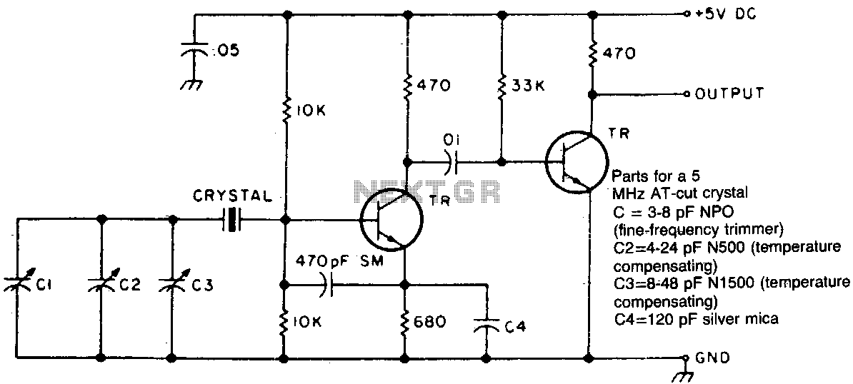
The circuit utilizes a combination of two negative-coefficient capacitors to achieve a specific capacitance adjustment. Negative-coefficient capacitors exhibit a decrease in capacitance with an increase in voltage or frequency, which can be beneficial in certain applications where frequency compensation is necessary.
In this configuration, the two capacitors are strategically selected and connected in such a manner that their individual characteristics complement each other. By blending these capacitors, the circuit can effectively counterbalance the natural decrease in frequency associated with standard AT-cut crystal oscillators. The AT-cut crystal is commonly used in oscillators due to its favorable temperature stability and frequency characteristics. However, as the frequency of operation shifts, the need for capacitance adjustment becomes critical to maintain performance.
The design may include a variable resistor or a potentiometer to fine-tune the capacitance further, allowing for precise adjustments based on the specific requirements of the application. This flexibility ensures that the oscillator remains stable across varying conditions, thereby enhancing the overall reliability and performance of the circuit.
Proper attention must be given to the selection of the capacitors, ensuring that their temperature coefficients and voltage ratings are suitable for the intended operating environment. Additionally, the layout of the circuit should minimize parasitic inductances and capacitances to maintain signal integrity. This approach not only optimizes the frequency response but also contributes to the longevity and efficiency of the electronic system.Two different negative-coefficient capacitors are blended to produce the desired change in capacitance to counteract or compensate for the decrease in frequency of the "normal" AT-cut characteristics. 🔗 External reference
Related Circuits
Figure a illustrates a multivibrator circuit capable of generating a square wave signal. Figure b depicts a flip-flop circuit that utilizes the falling edge of the input signal to produce a trigger pulse signal. Figure c represents a monostable...
The circuit operates in a parallel-fed configuration, as the DC plate current does not pass through the inductor. R3 can be substituted with an RF choke if desired. Capacitor C3 prevents B+ from appearing across the variable capacitor, which...

This circuit is designed to be housed in a compact plastic or preferably metal enclosure, powered by a 9V battery. It features a level control, a male XLR connector (similar to those used in microphones), and a switch. The...
A quadrature oscillator is a type of phase shift oscillator that produces two sine wave signals, with one signal shifted by 90 degrees from the other. The quadrature oscillator is commonly used in various applications such as signal processing, communications,...
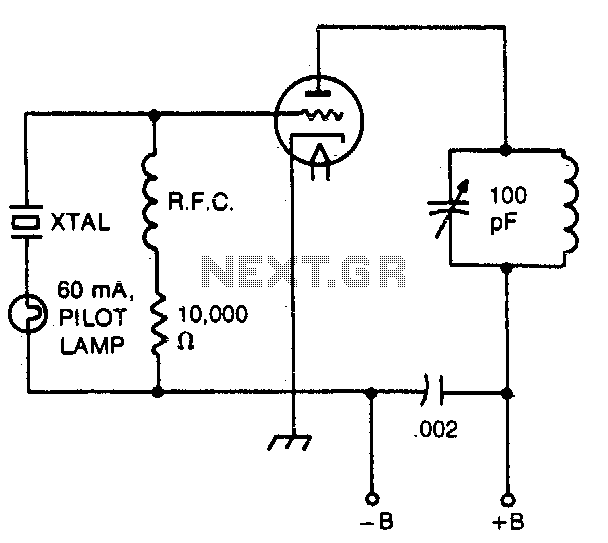
The pilot lamp limits current to prevent damage to the crystal. A very useful circuit. The circuit incorporates a pilot lamp designed to limit the current flowing to a crystal component, thereby safeguarding it from potential damage due to excessive...
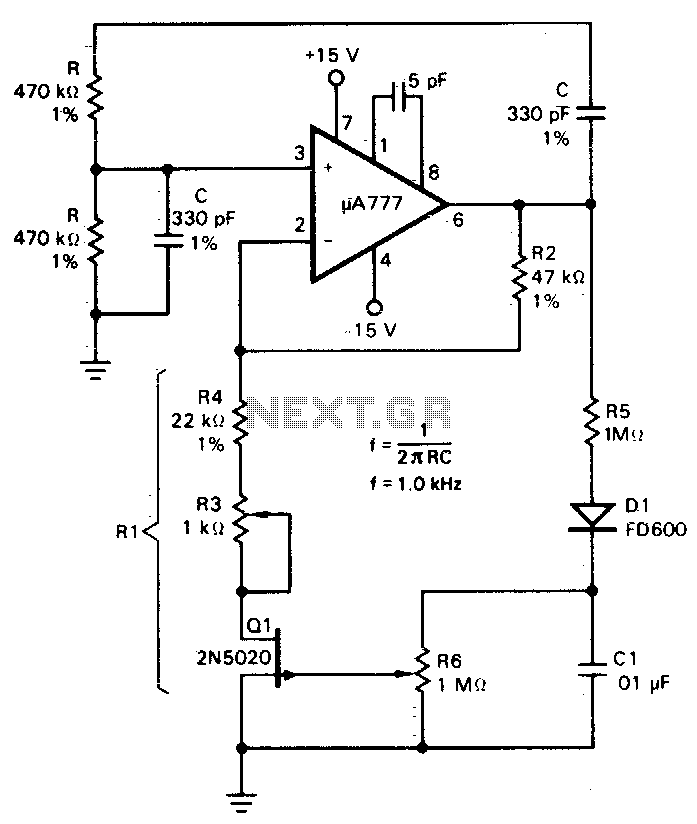
A field effect transistor (FET), designated as Q1, functions within the linear resistive region to facilitate automatic gain control. The attenuation of the RC network is one-third at the oscillation frequency with zero phase shift, necessitating that the amplifier...
Warning: include(partials/cookie-banner.php): Failed to open stream: Permission denied in /var/www/html/nextgr/view-circuit.php on line 713
Warning: include(): Failed opening 'partials/cookie-banner.php' for inclusion (include_path='.:/usr/share/php') in /var/www/html/nextgr/view-circuit.php on line 713