
Singing Tesla Coil
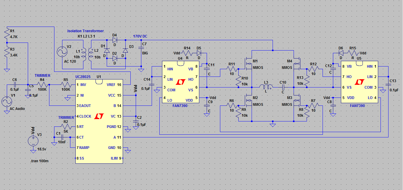
The implementation of an internal reference within an integrated circuit (IC) for audio biasing presents several advantages. By leveraging the chip's built-in voltage reference, one can establish a stable bias point for audio signals, which is crucial for maintaining audio fidelity and minimizing distortion. This method not only simplifies the design but also enhances reliability by reducing the number of external components required.
In typical audio circuit designs, biasing is essential for ensuring that the audio signal operates within the optimal range of the amplifier or processing stage. The use of resistors in conjunction with the internal reference allows for precise voltage division, enabling the designer to set the desired bias level effectively. The choice of resistor values will directly influence the bias voltage, and careful selection is necessary to achieve the intended performance characteristics.
Additionally, minimizing the parts count contributes to a more compact and cost-effective design, which is particularly important in consumer electronics where space and cost constraints are prevalent. This approach can lead to improved manufacturability and reduced assembly time, further enhancing the overall efficiency of the product development process.
Overall, utilizing the chip's internal reference in combination with resistors for audio biasing is a strategic design choice that optimizes performance while simplifying the circuit architecture. This method is particularly advantageous in applications where space, cost, and reliability are critical factors.That`s a great idea to use the chips internal reference and some resistance to get the right bias on the audio; it would really reduce the parts count 🔗 External reference
Related Circuits
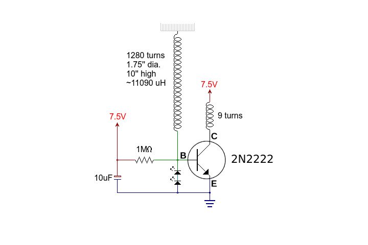
This circuit is straightforward. The accompanying graphics and images provide all necessary details. After gathering all materials, connect the transistor according to the provided schematic. The circuit in question is a basic transistor circuit that serves as an introductory project...
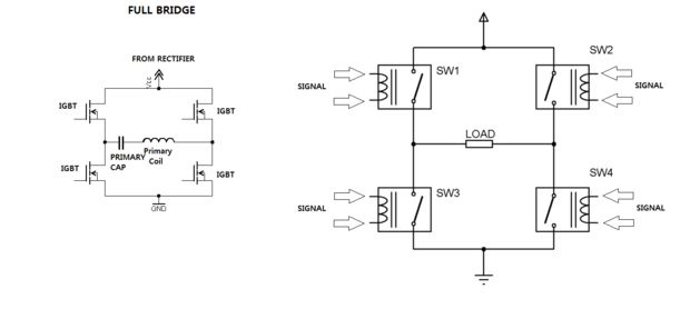
One of the most challenging aspects of constructing a solid-state Tesla coil is the bridge or switching circuit. The bridge switching circuit is the core component of the system. The bridge switching circuit is essential for controlling the power delivery...
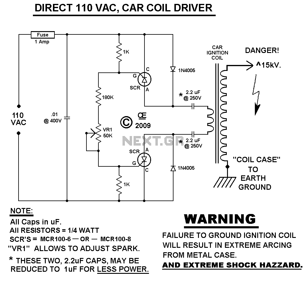
This Spark Can Be Very DANGEROUS, So BE CAREFUL. WARNING: FAILURE TO DO SO: WILL CAUSE THE CASE OF THE COIL TO ALSO BE ELECTRIFIED! NOTE You MUST have a LOAD on the High Voltage Output. With NO LOAD,...
The major project undertaken over the last few months involved constructing a small Tesla coil, a long-standing interest. The initial inspiration came from a demonstration at UNSW over a decade ago, leading to a fascination with the device. After...
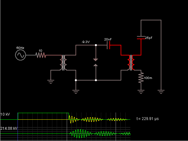
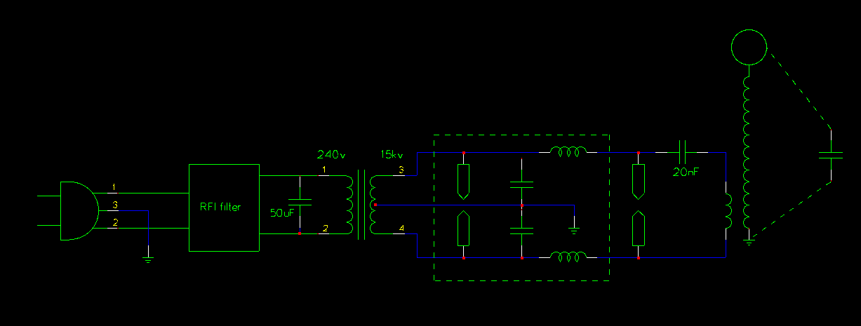
This is the Tesla Coil circuit diagram with a detailed explanation of its working principles. The electronic circuit simulator aids in designing the Tesla Coil circuit and simulating it online for better understanding. The Tesla Coil is a resonant transformer...
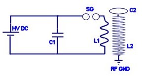
The history of Nikola Tesla and Tesla Coils, how a Tesla Coil works, and an example of a homemade Tesla Coil. The homemade DIY Tesla Coil is battery-operated and has a gas plasma discharge terminal. Arcs can be made...