
Video Selector Circuit
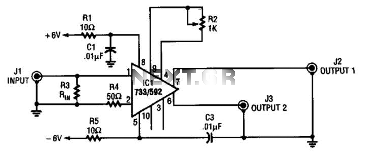
The circuit operates as a channel selector, utilizing electronic switches to determine which of the two input channels is connected to the output. The logic signal controls the state of the switches, allowing for seamless transition between channels. When one channel is active, the other is shorted to ground, effectively eliminating any potential interference or crosstalk that could affect the quality of the signal.
The design ensures that the bandwidth of the circuit remains stable, with a -3 dB point at around 8 MHz, making it suitable for various applications that require signal integrity within this frequency range. The choice of components, including the switches and any associated passive elements, should be carefully considered to maintain performance specifications.
Buffering the circuit is crucial, particularly when interfacing with a 75-Ohm load. The switches may introduce insertion loss, which could degrade the signal if not adequately addressed. By incorporating a buffer stage, the circuit can provide the necessary drive strength and impedance matching, ensuring that the output signal remains robust and undistorted. This additional buffering stage can be implemented using an operational amplifier configured as a voltage follower or a dedicated buffer IC designed for high-frequency applications.
Overall, this circuit is effective for channel selection in communication systems, where maintaining signal quality and minimizing crosstalk are critical for optimal performance. This circuit selects one of two channels with a logic signal. The unused channel is shorted out, which minimizes crosstalk. The bandwidth at -3 dB is about 8 MHz. It is advisable to buffer this circuit because there is some loss in the switches when feeding a 75-Ohm load. 🔗 External reference
Related Circuits
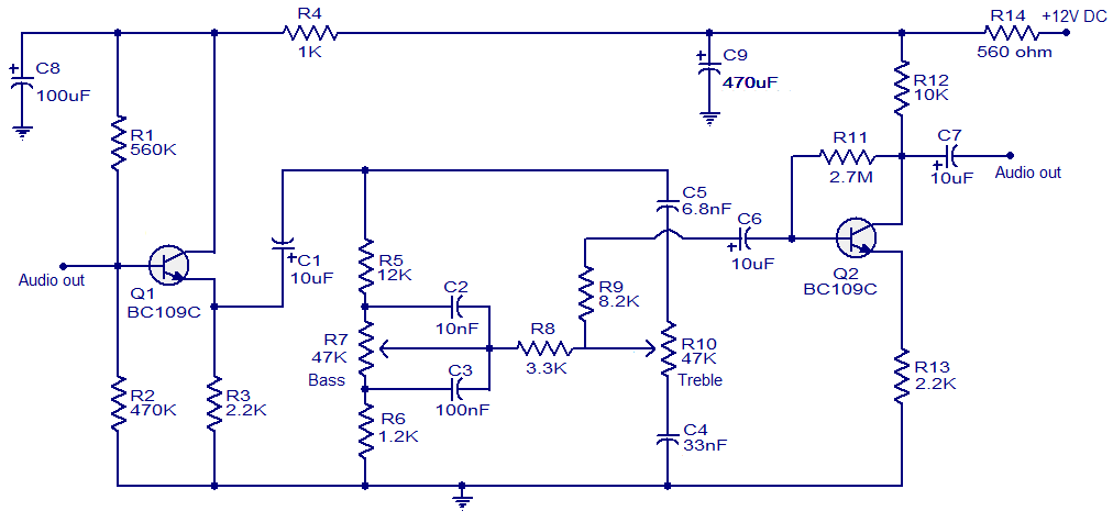
This simple tone control circuit is designed based on the renowned Baxendall tone control circuitry. The circuit can provide a maximum cut or boost of approximately 12 dB at both 10 kHz (treble) and 50 Hz (bass). Additionally, both...
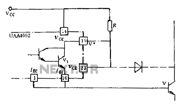
Anti-saturation devices have been removed from the UAA4002 routine applications. The base current of the switching transistor, which is driven by another transistor, is automatically adjusted. This adjustment allows the power transistors to operate in critical saturation. However, when...
This circuit can be used for detecting infrared light; for example, it is utilized for detecting infrared band light signals in a spectrophotometer. The amplifier output voltage Vo is given by the formula Vo = Is·Rd·Rf/Ri, where Is is...
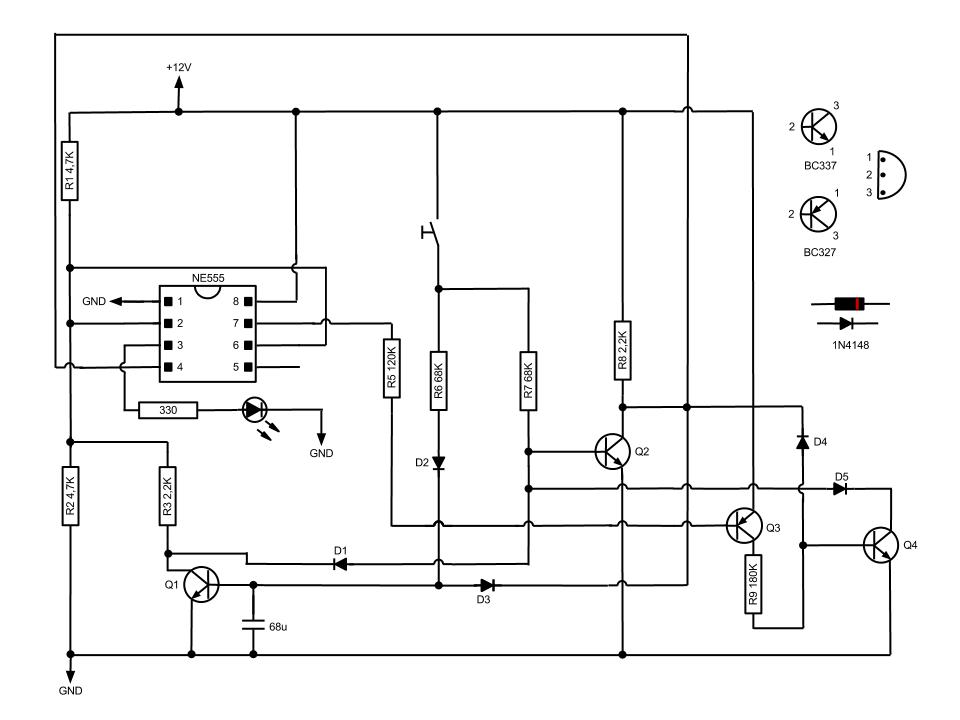
This circuit, based on the NE555 timer, activates and deactivates the IC output using a momentary switch. It functions similarly to a mechanical latching relay, but resets to its initial state when the power supply is turned off. This...
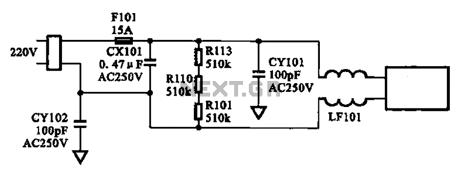
The AC input circuit consists of a fuse (Fl01), a mutual inductance filter (LF101), and filter capacitors (CX101, CY101, CY102), among other components. Its primary function is to filter out noise and pulse interference from the AC circuit, as...
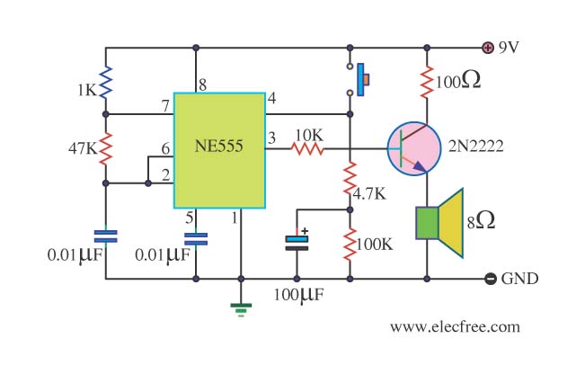
This is a danger beep circuit. It uses a 555 integrated circuit configured as a stable multivibrator that provides a duty cycle of 5% to drive a loudspeaker. The danger beep circuit utilizes the 555 timer IC, a versatile and...
Warning: include(partials/cookie-banner.php): Failed to open stream: Permission denied in /var/www/html/nextgr/view-circuit.php on line 713
Warning: include(): Failed opening 'partials/cookie-banner.php' for inclusion (include_path='.:/usr/share/php') in /var/www/html/nextgr/view-circuit.php on line 713