
Single Chip FM Transmitter
The described FM transmitter circuit functions as a bridge between a home entertainment system and a portable radio, allowing for seamless audio transmission throughout various spaces. The core component of this transmitter is IC1, a voltage-controlled oscillator (VCO) that utilizes an integrated varactor diode to modulate its frequency. This design enables the circuit to operate within the FM band, making it suitable for broadcasting audio signals.
The frequency of oscillation is primarily determined by inductor L1, which is specified at a value of 390nH. This inductance value is critical as it establishes a nominal frequency of approximately 100 MHz, which falls within the typical FM broadcasting range. The choice of this frequency is important to ensure compatibility with standard FM receivers, allowing for effective transmission and reception of audio signals.
Potentiometer R1 plays a pivotal role in tuning the transmitter to different channels across the FM band. By adjusting this potentiometer, the user can vary the voltage applied to the varactor, which in turn alters the capacitance and modifies the oscillation frequency of the VCO. This feature enables the user to select an appropriate channel that minimizes interference from other radio stations, thereby enhancing audio clarity and quality.
Additional components that may be present in the circuit include bypass capacitors to stabilize the power supply to the VCO, as well as coupling capacitors that ensure proper signal transmission while blocking DC components. An antenna, typically a simple wire or a whip antenna, is also essential for radiating the modulated signal into the surrounding environment, allowing the portable radio to receive the transmitted audio.
Overall, this simple FM transmitter circuit exemplifies an effective solution for wireless audio distribution, leveraging basic electronic components to achieve functionality that enhances the enjoyment of audio content throughout a home or outdoor setting.A simple FM transmitter links your home-entertainment system to a portable radio that can be carried around the house and into the back yard. For example, you can play music on the CD changer in your living room, and listen to it on a portable radio by the back-yard barbeque.
IC1 is a voltage-controlled oscillator with integrated varactor. Its nominal frequency of oscillation is set by inductor L1, and a 390nH value places that frequency at 100MHz. Potentiometer R1 then lets you select a channel by tuning over the FM band of 8 🔗 External reference
Related Circuits
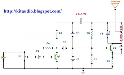
The following diagram is the schematic diagram of a four-transistor FM transmitter circuit designed by Paul K. Sherby. Components List: R1, R2, R8 = 1K, R3 = 100K, R4 = 150K, R5, R7 = 10K, R6 = 220 ohm,...
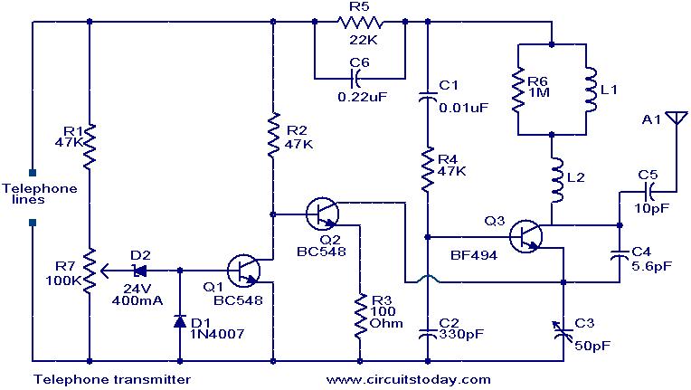
This circuit is a simple yet effective design for transmitting telephone conversations. When the telephone receiver is on-hook, the voltage across the lines is approximately 48 volts. The preset resistor R7 is adjusted to achieve a voltage of 24.7...
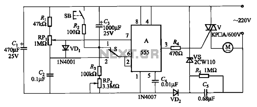
The circuit illustrated in Figure 3-12 incorporates variable speed and timing control functions. When switch S is set to position 1 and button SB is pressed, the motor initiates operation. After a predetermined delay, the motor automatically shuts down....
The circuit is a radio frequency (RF) oscillator functioning at approximately 100 MHz. Audio signals captured and amplified by an electret microphone are routed to an audio amplifier stage constructed around the first transistor. The output from the collector...
This is a small but quite powerful FM transmitter having three RF stages incorporating an audio preamplifier for better modulation. It has an output power of 4 Watts and works off 12-18 VDC which makes it easily portable. It...
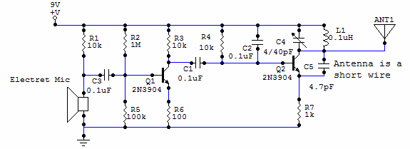
This circuit uses a small microphone to capture the sound and some transistors to generate radio waves that can be picked up by a FM receiver like a car stereo. The first part is the microphone and some resistors...