
Stair case wiring circuit diagram OR How to control a lamp from two different places by two 2-way switches

The staircase circuit, commonly referred to as a two-way switching circuit, utilizes two switches to control a single load, such as a light bulb, from two different locations. This configuration is particularly useful in staircases or long hallways where accessibility to a switch from both ends is desired.
In the typical wiring setup, the two switches are connected in a way that allows them to control the same light fixture. Each switch has three terminals: one common terminal and two traveler terminals. The common terminal connects to the power source or the load (the bulb), while the traveler terminals connect to the corresponding traveler terminals of the other switch.
When the first switch is toggled, it either connects or disconnects the circuit, allowing current to flow to the bulb or interrupting it. The second switch can then be used to reverse the state of the bulb, effectively allowing the user to turn the light ON or OFF regardless of the position of the other switch. This creates a versatile control system that enhances convenience and safety in areas where lighting is essential.
In summary, this two-way switching circuit enables efficient control of lighting from multiple locations, ensuring that the user can operate the light fixture from both the upper and lower positions of the staircase. The design promotes ease of use and flexibility in lighting control, making it an essential feature in modern electrical installations.You can see that circuit is complete and bulb is ON. Suppose you want to OFF bulb from the upper switch at top of stair, simply Switch OFF the switch then circuit will break and the bulb will be OFF. You can switch ON the bulb again to switch ON this Switch. In other words you can OFF and ON bulb from upper switch at the top of stair. Obviously; you can do same from the upper and bottom switch, so let`s see how we can do that from that switch at the bottom of stair. Now return to circuit again in the pic, In this case you can see that circuit is complete and bulb is ON.
Suppose you want to OFF the bulb from the lower switch at bottom of stair. Simply OFF the switch, then again circuit will break and the bulb will be OFF. You can switch ON the bulb again to switch ON this Switch This is a stair case circuit diagram by which we can control a bulb from two different places. We can switch OFF and Switch ON the bulb from both switches at the same time. in other words we can control (OFF or ON) the bulb from upper and lower switches. 🔗 External reference
Related Circuits
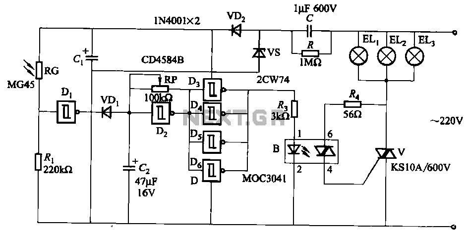
The circuit utilizes a CD4584B six Schmitt trigger integrated circuit (IC) with components Di and Ri forming a photometric circuit. D2, along with RP and C2, comprises an adjustable frequency ultra-low frequency oscillation device, where RP serves as an...
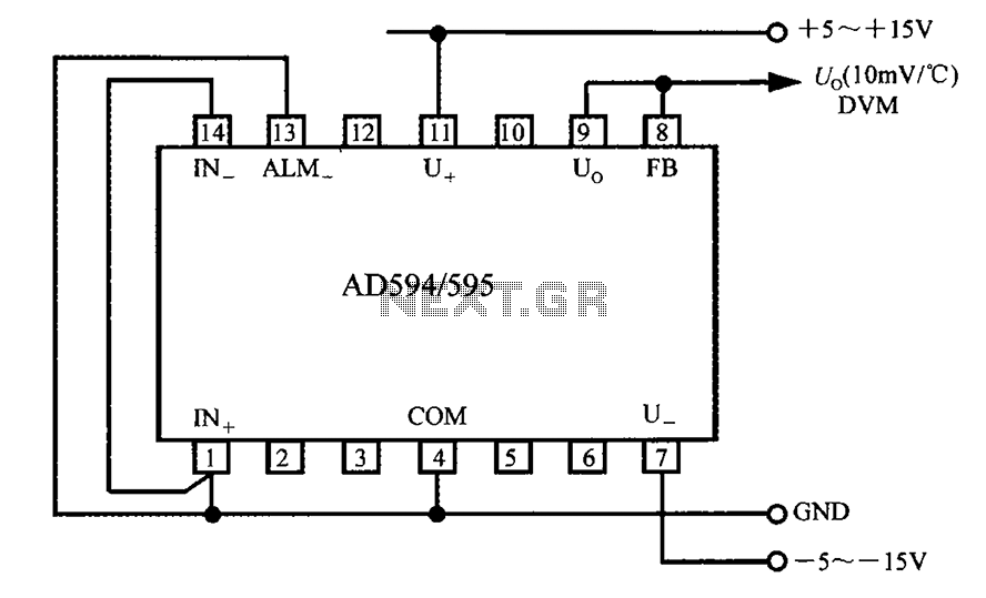
The AD594/595 can be configured to measure temperature in Celsius. In the circuit diagram, the IN+ and IN- terminals should be shorted to the COM terminal. The output voltage (Uo) has a temperature coefficient of 10 mV/°C, which can...
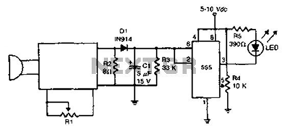
The acoustic detector consists of a Schmitt trigger IC555 connected to various components. When the input exceeds a certain voltage, the output will change state from high to low. R4 is used to set the threshold voltage. The acoustic detector...
To obtain the power supply graphs on the previous page, the circuit is designed to independently monitor the power sources with the addition of a few resistors. Diode D3 allows the solar panel voltage to charge the batteries, while...
This AC to DC power supply can output 5A in continuous operation and 12A peak current. This type of DC power supply uses a PCB, allowing for two case types for IC1: TO-220 or TO-3. The regulation of this...
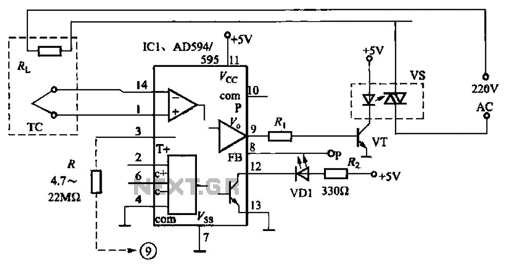
An automatic electric furnace temperature controller is depicted in FIG. 1-25. The closed circuit is established through a temperature detection output control loop. As the temperature rises, the output voltage increases. When the voltage reaches a preset temperature value,...