
Slave Flash Trigger

In electronic circuit design for camera systems, the integration of supplementary lighting is crucial for improving visibility in low-light conditions. A common solution involves the use of LED (Light Emitting Diode) arrays, which provide efficient illumination while consuming minimal power. The circuit typically includes a power supply unit, a control circuit, and the LED array.
The power supply unit must be designed to convert the available voltage to the required level for the LEDs, taking into account the forward voltage and current specifications for the chosen LED components. A DC-DC converter can be employed for this purpose, ensuring that the LEDs receive a stable voltage and current, thus prolonging their lifespan and maintaining consistent brightness.
The control circuit can be implemented using a microcontroller or a simple transistor-based switch. If using a microcontroller, it can be programmed to adjust the brightness of the LEDs based on ambient light conditions, using a light-dependent resistor (LDR) as a sensor. The LDR detects the level of surrounding light and sends this information to the microcontroller, which then modulates the LED brightness accordingly. This allows for optimal illumination without excessive power consumption.
In summary, the design of a supplementary lighting circuit for cameras in low-light environments involves careful consideration of power management, control mechanisms, and component selection to ensure effective performance and energy efficiency.Using any camera in a dull or dark environment generally requires the use of supplementary light. This is a standard technique, and even where adequate na.. 🔗 External reference
Related Circuits
Capacitors C1 and C2, in conjunction with a speed controller, function by receiving voltage at the gate of the MOSFET. When the voltage on C is applied, it activates the operation of the MOSFET. In this circuit configuration, capacitors C1...
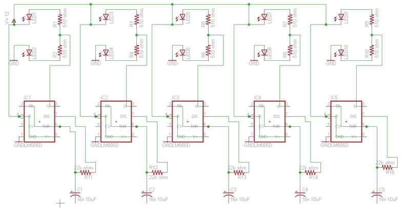
Build a circuit that will flash five pairs of LEDs at variable rates. To achieve this, a circuit utilizing five NE555 timers has been designed. Trim pots will be used to control the variable flash rate. Assistance is needed...

Using any camera in a dull or dark environment generally requires supplementary light. This is a standard technique, even when adequate natural lighting exists, to take conventional film pictures with enhanced contrast using a fill-in flash for foreground subjects...

The reason why I built this unit is because I need to trim my transmitters for the best performance. I have noticed that I can't be at the receiver position and the transmitter position at the same time. So,...
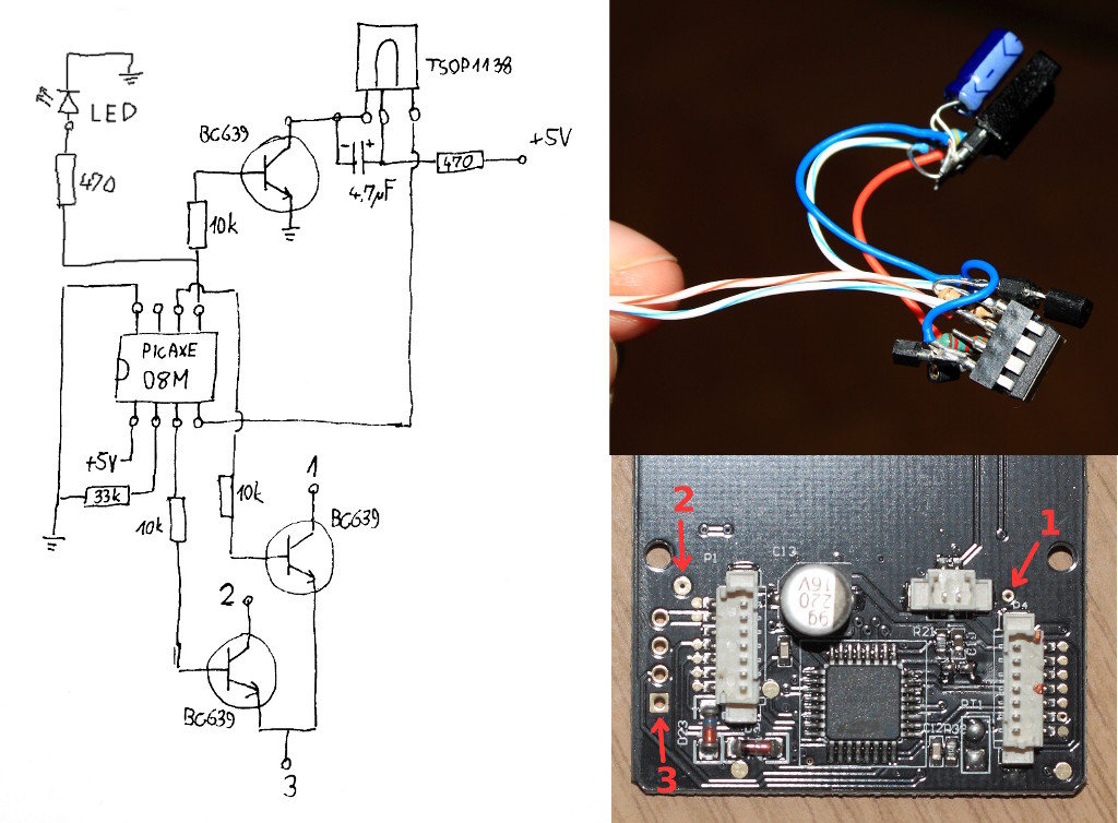
The YN-460 is an affordable manual-only shoe mount flash produced by the Chinese company Yongnuo. It has gained popularity within the strobist community primarily due to its low price and satisfactory performance. To adjust the flash power level, users...

The schematic consists of four hardware blocks: 1) The wall transformer 2) The charging circuit 3) The control unit 4) The output stage. The circuit schematic is structured around four essential hardware blocks that facilitate the overall functionality of the...