
slow down a fuel pump
Warning: Undefined array key "extension" in /var/www/html/nextgr/view-circuit.php on line 477
Deprecated: strtolower(): Passing null to parameter #1 ($string) of type string is deprecated in /var/www/html/nextgr/view-circuit.php on line 477

To reduce the fuel flow from the external pump, a few methods can be considered. One effective approach is to implement a resistor in series with the fuel pump. This will limit the current flowing to the pump, consequently reducing its output pressure and flow rate. It is essential to select a resistor with appropriate wattage ratings to handle the power dissipation, as the pump operates at a significant current draw.
Alternatively, a PWM (Pulse Width Modulation) controller can be employed to modulate the voltage supplied to the fuel pump. This method allows for more precise control over the pump's speed and flow rate, providing flexibility for varying engine demands. The PWM controller can be configured to adjust the duty cycle, effectively controlling the average voltage and current supplied to the pump.
Furthermore, modifying the fuel return line can also influence the flow rate. By incorporating a restrictive fitting or valve in the return line, the pressure drop across the pump can be increased, resulting in reduced flow. However, care must be taken to ensure that the fuel pressure regulator can still maintain the required pressure for optimal engine performance.
In summary, reducing the flow from an external fuel pump can be achieved through the use of resistors, PWM controllers, or modifications to the fuel return line. Each method has its advantages and considerations, and the selection of the appropriate technique will depend on the specific requirements of the engine and fuel system configuration.You can get booster for fuel pumps to increase their rating, but is it possible to do anything to the wireing of an external pump to get it to flow LESS fuel Reason I ask is I am helping my brother out with an engine swap (admittidly, its not a rotary, or an RX7 for that matter). We have put a 4AGE in his KE35 carolla. The fuel system is a lift pump, surge tank and 500hp feel pump. Factory 4AGE FPR. you could run a restrictive return line back to the tank from before the regulator but thats some macgyver *. or you could trade pumps with someone with something smaller. I have a s5 na pump A note on using resistors - your pump probably pulls around 7 or 8 amps at 12 volts and 40psi.
You will end up with very large wattage resistors which are not exactly cheap. you can see in this circuit diagram that, from the factory, the resistor relay is supplied voltage from the circuit opening relay through a lightblue/red wire. The wire branches off into two sections. With the resistor relay off (coil disengaged such as at idle), it passes through the resistor inside the box and comes out one of the light blue wires.
When the ECU wants to run the pump in high speed mode, the coil in the relay is engaged by a ground supplied by the Green/Red wire. The current now passes through the path of least resistance, through the other matching pair of light blue/red and light blue wires.
Because the wires are two pairs (light blue/red and light blue) of the same colors, you would want to check for resistance across each pair to determine which wires to use. One pair (the two wires you want to use) should have some decent level of resistance because it passes through the internal resistor.
I believe the other should be open circuit unless you trigger the relay by supplying power and ground to the black/white and green/red wires. It sounds more complicated than it is. just put the resistor pack inline with the fuel pump wire you have on this car. Two wires and you`re done. If you pick the wrong set, it won`t work. 🔗 External reference
Related Circuits
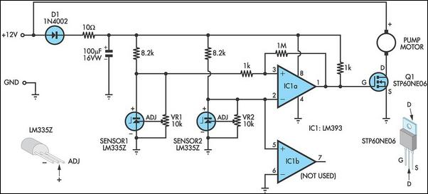
This circuit optimizes the operation of a solar hot water system. When the water in the solar collector is hotter than the storage tank, the pump runs. The circuit comprises two LM335Z temperature sensors, a comparator, and a MOSFET....
It is advisable to remove the glass from the regulator to allow for free movement of the regulator, and then reattach the glass after the motor installation. Once the motor is installed, operate the regulator with the motor to...
Realistic flap and landing gear actuation. This circuit slows the speed of a conventional proportional servo. It regulates the time required for full servo rotation from 1 to 10 seconds without any reduction in the servo's torque, and every servo...
This moisture detector with pump controller is built around the special purpose LM1830 IC. The LM1830 is designed to detect moisture by passing an AC current through a set of probes. An internal comparator compares the resistance of the...
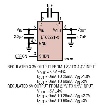
The LTC3221 family consists of micropower charge pump DC/DC converters that deliver a regulated output of up to 60mA. The input voltage range is from 1.8V to 5.5V. With an extremely low operating current of 8µA typical at no...
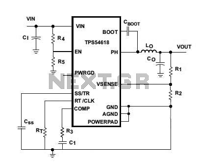
Texas Instruments introduced the TPS54618, a 6-A step-down SWIFT DC/DC converter. The new TPS54618 is a monolithic synchronous switcher featuring two integrated 12-milliohm MOSFETs. The TPS54618 is designed to provide high efficiency and compact solutions for powering a variety of...