
small general purpose audio
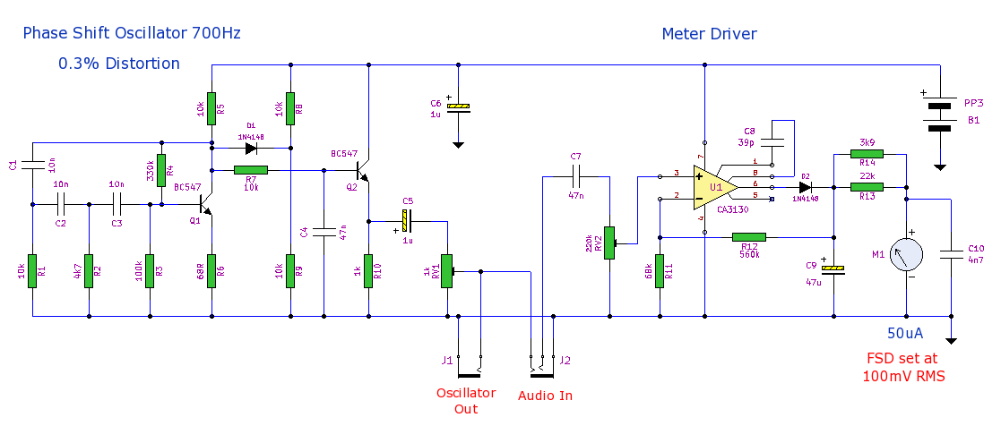
1) The oscillator output level is always visible on the meter until a 3.5mm mono plug is inserted into the audio input socket, which interrupts the monitoring and allows the user to connect their own audio signal.
2) Two multiturn trimpots control the oscillator output level, adjustable up to several hundred millivolts RMS, and the sensitivity of the meter driver. Both of these circuit components are open to modification. The meter’s FSD is intentionally limited to 100mV RMS for specific reasons. The 3.9kΩ and 22kΩ resistors in parallel with the meter are also beneficial; if one end of the 3.9kΩ resistor is unsoldered, the meter can handle external audio line level inputs of up to a couple of volts RMS. Furthermore, the audio bandwidth of the meter driver, currently limited to speech frequencies, can be expanded to 10kHz for testing systems or modules by changing capacitor C8 from 39pF to 10pF.
3) It is crucial to note that computer and laptop sound cards have highly sensitive inputs. The costs of replacing laptop motherboards are significantly high. Signals exceeding 150mV RMS can potentially damage the sound module, especially if they consist of high instantaneous pulses. The software microphone boost switch should always be disabled, and the fader should be set to approximately one-third of its maximum position.
4) If the signal to be monitored and analyzed is very high, it is advisable to use a resistor attenuator before connecting to the PC. Additionally, incorporating two reverse-wired silicon diodes as a safety interface across the laptop microphone input socket is recommended. These diodes will clip signals to approximately 0.6 volts without affecting smaller test signals around 80mV RMS.
The prototype phase shift oscillator's spectrum can be viewed using Visual Analyzer software, with the signal applied to the laptop's microphone input socket or a line input if available. Basic calibration of the test set meter driver, which is internally paralleled with the oscillator output, can be performed by connecting it to the probes of a small digital pocket multimeter, such as a Beckman. This multimeter is capable of auto-ranging sensitivity, allowing readings from 0 to 2V AC. To achieve a full-scale deflection of 100mV RMS on the meter, the Beckman must display approximately "90" (i.e., 90 x 1.11 = 99.9, which is sufficiently close). The meter scale FSD preset potentiometer can then be adjusted accordingly. To confirm linearity, the test set scale can be verified at critical points using the multimeter. This method concludes the calibration process, although an alternative approach involves using a known output from another sine tone source, such as that provided by PC audio software, to set the phase shift oscillator’s output to the desired level.This is a small general purpose audio test set. It comprises a low 0. 3% distortion phase shift oscillator and a level meter. The level meteris set at 100mV FSD and can be used for gain measurements and general testing. Current consumption is just under 4mA. The oscillator is a phase shift based around Q1 and associated components. Frequency is set at 700Hz by C1, C2, C3, R1, R2 and R3. The sinewave appears at the collector of Q1 and the amplitude is stabilized by D1 and the voltage tap R8 and R9. The sine wave is buffered by Q2 which will also reduce output impedance of the oscillator. R7 and C4 form a low pass single pole harmonicfilter the oscillator signal is adjustable by preset VR1 and appears at the 3.
5mm jack socket, J1. The following comments and caveats that come to mind, help the user of the finished itemparticularly when used with pcs and laptops for which this test set was intended. Items 3 and 4 are not aimed at being alarmist, but should be treated with serious caution. 1) The applied/terminated oscillator level is always available to be seen on the meter. That remains so until a 3. 5mm mono plug is inserted into the audio IN socket. This breaks the monitoring and lets the user apply their own audio signal. 2) Two multiturn trimpots control both the required oscillator output level up to a few hundred millivolts rms and the meter driver sensitivity.
Both circuit parts are obviously open to modification. Meter FSD is deliberately restricted to 100mV rms for the reasons stated in item 3. The 3k9 and 22k in parallel to the meter are also useful. If one end of the 3k9 is unsoldered, the meter will cope with external audio line level input, up to the order of a couple of volts rms. Also the meter driver audio bandwidth which currently is only for speech, can be usefully widened to 10khz for system or module testing purposes, by reducing C8 to 10p from 39p.
3) Be advised that computer and laptop soundcards have very sensitive inputs. Motherboard replacement costs of laptops are hugely prohibitive! Signal much over 150mV rms will result in almost certain destruction of the sound module, particularly if of a very high instantaneous pulse nature. The software microphone boost switch MUST always be off and fader kept to only about 1/3 up from the bottom.
4) It is strongly recommended that if the wanted signal to be viewed and analysed is very high, then that signal should be fed through a resistor attenuator before entering the pc. In addition, two reverse-wired silicon diodes are suggested to be included in a safety interface across the laptop microphone input socket.
These will clip to about 0. 6volts, but shouldn`t have any effect on smaller test signals of around 80mV rms. The image below shows the spectrum of the prototype phase shift oscillator viewed on Visual Analyser. The signal was applied to the microphone input socket on my laptop, but can be applied to a line input if one is available.
More free software for windows and linux available below. No frills audio tools & toys in Techmind. Downloads here:. The newest spectrum analyser version here: Basic calibration of the test set meter driver internally paralleled with the oscillator output, is by connection to the probes of a small digital pocket multimeter such as a Beckman shown in the above photo. This particular instrument has useful auto-ranging sensitivity to read down from 0 to 2V AC. Therefore if the variable output setting of the oscillator to the multimeter and meter driver together is to show 100mV RMS full scale deflection, the Beckman must display "90".
ie. 90 x 1. 11 = 99. 9 which is close enough, so the meter scale FSD preset pot can then be set correctly. To confirm linearity, the test set scale can then be tracked along its important points using the multimeter. This concludes this calibration method, but alternatively use the known reliable output from another sine tone source such as included in pc audio software.
The phase-shift oscillator can then have its preset output, set to read whatever level is required. 🔗 External reference
Related Circuits
When the resistance value of temperature, light, pressure, or any other resistive sensors (Rs) drops below a certain threshold, which can be adjusted by a preset. In electronic circuits, resistive sensors such as thermistors, photoresistors, and piezoresistors are commonly used...
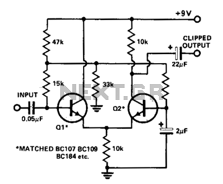
A differential amplifier serves as an effective audio clipper, capable of delivering precise and symmetrical clipping. The circuit presented begins clipping at an input voltage of 100 mV, with the output starting to clip at ±3 V. For optimal...
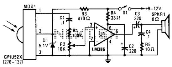
This circuit utilizes an infrared pulse-to-audio converter to assist in troubleshooting infrared remote controls, making it an effective tool for detecting infrared light sources. It employs a photo cell module (Radio Shack P/N 276-137) to detect IR radiation and...
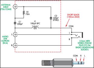
This document presents a concept for a low-cost adapter that enables the connection of a portable FM radio or MP3 player with an FM tuner to an external antenna and audio equipment, such as a hi-fi system or PC...
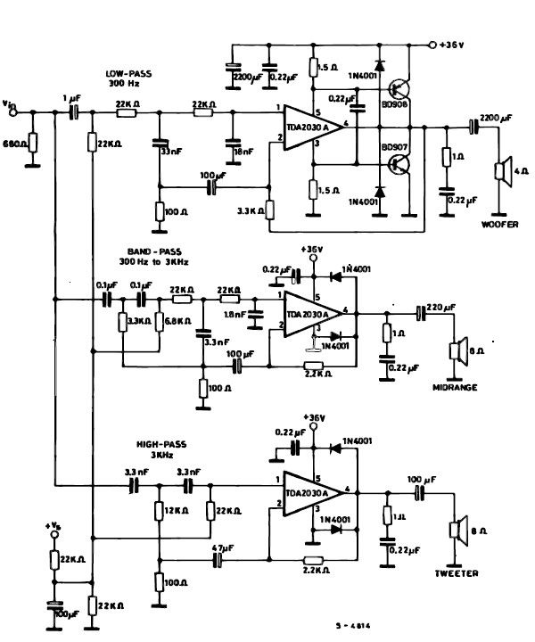
A simple multiway active speaker audio system can be designed using the TDA2030 audio IC. This TDA2030 active speaker audio system circuit is created to deliver optimal acoustic performance, as each loudspeaker is specifically designed and optimized for a...
Two inputs, A and B, control the bridge. With both high (or open circuit) both ends of the motor are connected to 0v. Connect A low and Tr2 turns on causing the motor to go forward. Connect B low...