
Stereo FM Transmitter with BA1404
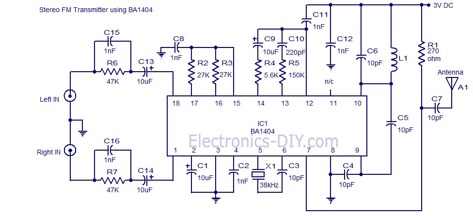
The high-quality stereo FM transmitter circuit based on the BA1404 IC is designed to provide efficient transmission of audio signals with minimal distortion and optimal stereo separation. The BA1404 integrates multiple functionalities, which simplifies the overall design while ensuring robust performance. The operating frequency range of 76 to 108 MHz is suitable for standard FM broadcasting, making this circuit applicable for various audio transmission projects.
The pre-emphasis network, composed of resistors (R6, R7) and capacitors (C13, C14, C15, C16), is crucial for enhancing the signal-to-noise ratio during transmission. By boosting higher frequencies, this network compensates for the inherent limitations of FM receivers, which typically exhibit reduced sensitivity to high-frequency audio components. This careful tuning ensures that the transmitted audio maintains clarity and fidelity when received.
The oscillator circuit, formed by inductor L1 and capacitor C5, determines the carrier frequency of the FM signal. The precise selection of these components is essential, as it directly influences the stability and quality of the transmitted signal. The inclusion of the 38 kHz crystal (X1) provides a stable reference frequency, which is fundamental for generating a consistent composite stereo signal. This reference frequency is pivotal for ensuring that the stereo modulator operates effectively, allowing for accurate transmission of stereo audio signals.
The additional network comprising capacitors (C9, C10) and resistors (R4, R5) plays a significant role in improving channel separation, which is vital for maintaining the integrity of the left and right audio channels. This enhancement minimizes crosstalk between channels, ensuring that the listener experiences a clear and distinct stereo soundstage.
Overall, this stereo FM transmitter circuit exemplifies a well-engineered solution for audio transmission, combining advanced modulation techniques with careful component selection to achieve high-quality performance in FM broadcasting applications.A high quality stereo FM transmitter circuit is shown here. The circuit is based on the IC BA1404 from ROHM Semiconductors. BA1404 is a monolithic FM stereo modulator that has built in stereo modulator, FM modulator and RF amplifier. The FM modulator can be operated from 76 to 108MHz and power supply for the circuit can be anything between 1.25 to 3 volts.
In the circuit R7, C16, C14 and R6, C15, C13 forms the pre-emphasis network for the right and left channels respectively. This is done for matching the frequency response of the FM transmitter with the FM receiver. Inductor L1 and capacitor C5 is used to set the oscillator frequency. Network C9,C10, R4,R5 improves the channel separation. 38kHz crystal X1 is connected between pins 5 and 6 of the IC. Composite stereo signal is created by the stereo modulator circuit using the 38kHz quartz controlled frequency
🔗 External reference
Related Circuits
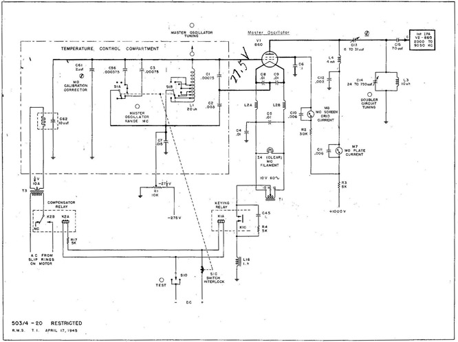
With the equipment ready for operation, the main line switch (S-831), the emergency switch (S-12), and the main line contactor contacts (K-831B) are all closed. The keying relay main contacts (K-1C) ground the center tap of the MO filament...
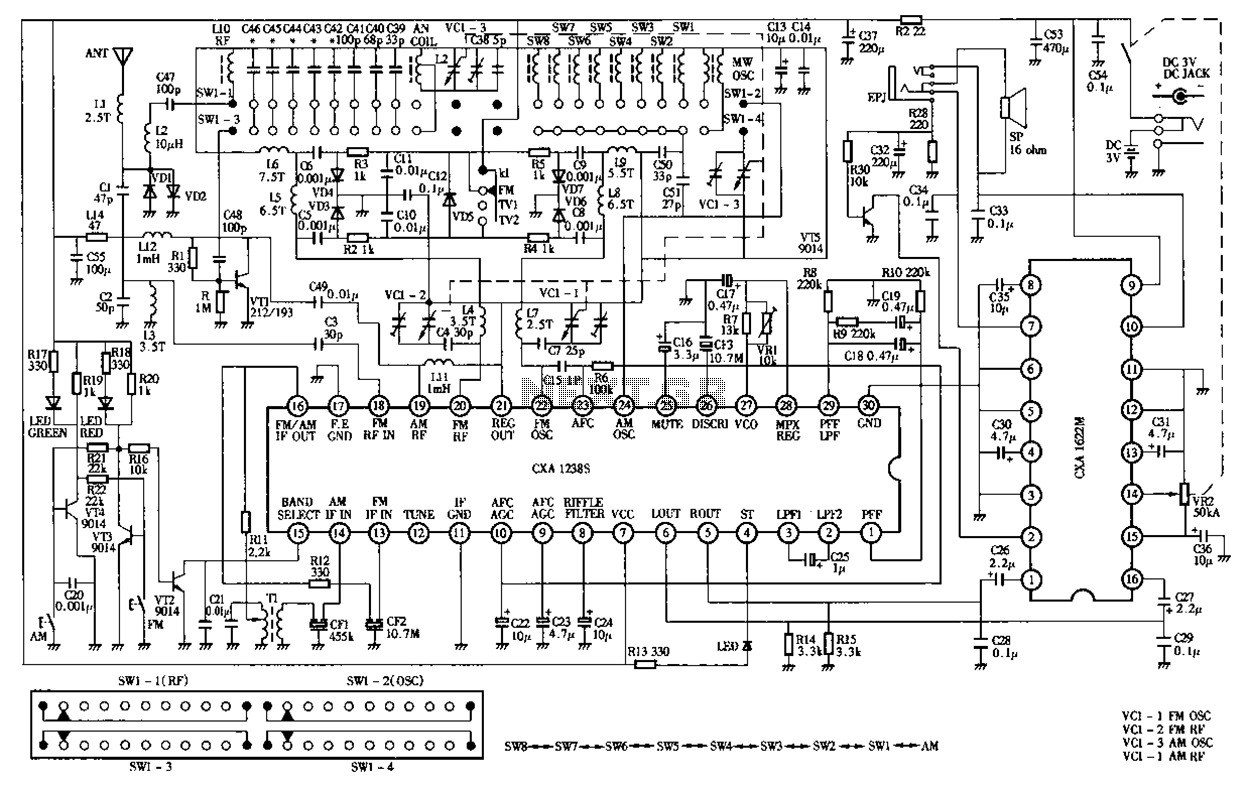
Desheng Rl212A 12-band FM, MW, SW, television sound stereo radio circuit diagram as follows: The Desheng Rl212A is a versatile radio circuit designed to operate across 12 different frequency bands, including FM (Frequency Modulation), MW (Medium Wave), and SW...
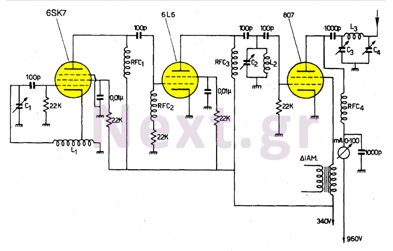
This transmitter operates in the shortwave range from 6 MHz to 22 MHz. Coil L1 serves as the shortwave oscillating coil for the 6SA7 vacuum tube and is commercially available. Capacitor C1 is a variable capacitor with a capacitance...
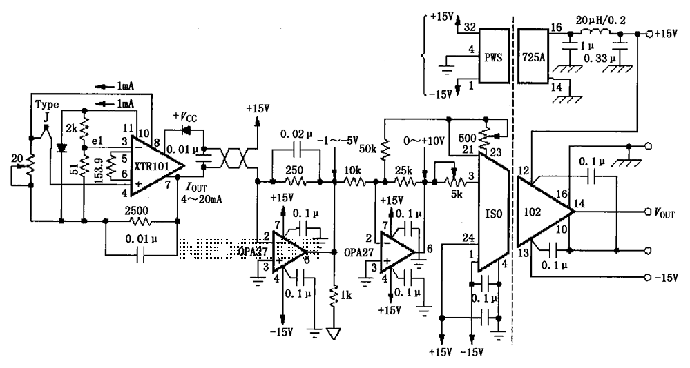
The circuit depicted in the figure features the ISO102 and XTR101 components, forming an isolated remote transmitter circuit equipped with isolated thermocouple cold-junction compensation. The circuit comprises four main parts: the current loop amplifier XTR101, the isolation amplifier ISO102,...
This frequency of this transmitter is PLL controlled which makes it very stable. The frequency is programmed in digitally way and can be changed very easy. Frequency range is about 50 to 150 MHz and the output power 100mW....
This circuit is designed for low power operation and can be tuned to function within the frequency range of 87-108 MHz, achieving a transmission distance of 20 to 30 meters. The circuit utilizes a pair of BC548 transistors, which,...