
Softrock Lite II
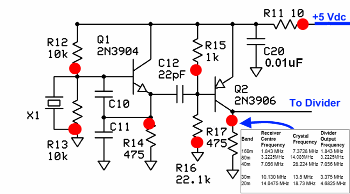
The Local Oscillator (LO) stage utilizes a Colpitts Crystal Oscillator configuration, which is known for its stability and reliability in generating precise frequencies. The oscillator is designed to operate at the fundamental frequency specified by the crystal, although practical implementations may yield a frequency that is slightly lower due to the influence of the capacitive divider formed by capacitors C10 and C11. This frequency pulling effect is more significant in higher frequency bands, impacting the oscillator's performance.
In the context of the 30m, 20m, and 15m bands, the LO produces a frequency that is 4/3 times the intended center frequency, contrasting with lower band models that achieve a 4x output. The LO generates a 13.5 MHz output signal, which is subsequently divided by 4, resulting in a 3.375 MHz square wave. This square wave contains odd harmonics that are significant for the mixing process. The mixer receives both the fundamental frequency of 3.375 MHz and its third harmonic, which is calculated as 10.125 MHz. The Bandpass Filter (BPF) is critical in ensuring that only the desired frequency components pass through to the mixer, effectively filtering out unwanted signals centered around the 3.375 MHz frequency.
Proper mounting of components, particularly the HC49 crystal, is essential for optimal performance. The crystal should be mounted vertically to enhance stability, with careful attention to grounding to prevent short circuits. The grounding wire not only provides electrical grounding but also serves as mechanical support, ensuring that the crystal remains securely in place.
Voltage measurements taken at various points in the circuit may reflect both AC and DC components, which can lead to discrepancies in expected voltage readings. The measured DC voltage at R17 is approximately 2.6 VDC, but this value is not critical and can vary based on the specific crystal used. The primary objective remains the generation of a robust RF output that can be easily detected by external receivers or measurement equipment.
For lower frequency bands, the LO's output frequency is designed to be four times the desired center frequency, while for the higher band kits, the output is adjusted to approximately 3/4 of the crystal frequency. The trade-off in sensitivity due to the use of 1/3 sub-harmonic sampling is compensated by increased gain in the I/Q audio stage, utilizing an LT6231 op-amp for enhanced performance compared to previous configurations. This design approach ensures that the receiver maintains adequate sensitivity across different frequency bands while adhering to the specific operational requirements of the circuit.The Local Oscillator stage implements a basic Colpitts Crystal Oscillator with a buffer stage to increase the signal level. The oscillator produces a signal that is at the crystal`s specified fundamental frequency. In reality, for each frequency the crystal circuit will oscillate at a slightly lower frequency (~ - 1 kHz), due to the capacitive div
ider (C10/C11) pulling the crystal down somewhat. The effect is more pronounced for the higher bands. Alan, G4ZFQ points out that on the 30m, 20m, 15m receivers, the Local Oscillator produces a signal that is 4/3 times the desired center frequency as opposed to the 4x the center frequency output for the lower band models. "Subharmonic" works like this:- The LO outputs a 13. 5MHz signl that goes to the dividers /4, resulting in 1 3. 375MHz square wave ( rich in odd harmonics) being fed to the mixer. At the mixer, a strong 3rd harmonic is present on the clock inputs, along with the fundamental of 3. 375 MHz. The 3. 375 fundamental multiplied by 3 yields the third harmonic of 10. 125MHZ. The Bandpass filter (BPF) performs the essential function of severely attenuating any signals centered around the 3.
375MHz fundamental frequency and first harmonmic, but allows 30m signals centering around the third harmonic of the 3. 375MHz LO output. The result is that the mixer is dealing with signals in the passband, centering on 10. 125MHz, as though the dividers were passing a fundamental frequency of 10. 125 to the mixer. BPFs are all that stop Softrocks from working on unwanted frequencies! Mount the HC49 crystal mounting in the upper left corner of the board, mounting it vertically to the board.
A small plated-through hole in the lower left corner of the crystal mounting position provides a place for a grounding wire to be soldered to the metal crystal case. The grounding wire also provides additional mechanical support for the crystal. Make sure the crystal is mounted slightly above the board. You can use a piece of cardboard or wire insulation between the bottom of the crystal and the board to get the desired standoff distance while mounting X1.
This can help prevent the two plated holes beneath the crystal from shorting out on the crystal case. Note that some of the voltages measured may have ac components, which, depending upon your DMM, may average in with the dc voltages to produce higher apparent dc voltages than theory would suggest.
Author measured the dc voltage at R17 using a scope and got ~2. 6 Vdc. Per Alan, G4ZFQ, This voltage (at R17) is not critical and can vary a lot, partly depending on the crystal. The important thing is that the LO`s RF output is a good healthy signal and is detectable on an external RX (or counter or scope).
On the 3 lower bands, the frequency of the LO`s output should be 4 times the desired center frequency e. g. , 28. 224 MHz for a desired center frequency of 7. 056 MHz). If your kit is the 30m, 20m, or 15m kit, this is a little different. The higher band SoftRock Lite kits use 1/3 sub-harmonic sampling to give receive function. The center frequency is approximately 3 * XtalFrequency / 4 in MHz. The loss in sensitivity associated with the 1/3 sub-harmonic sampling, about 3 or 4 dB, is made up by 5x gain, (compared to the lower band SoftRock Lite kits), in the I / Q audio stage where a low-noise LT6231 op-amp is used in lieu of the TVL2462CD opamps
🔗 External reference
Related Circuits
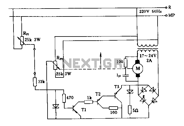
The FIG potentiometer RP2 has a sliding contact that is directly connected to the antenna. The system operates such that only when potentiometers RP1 and RP2 are positioned identically, do the non-conductive transistors and rectifier bridge remain off, resulting...
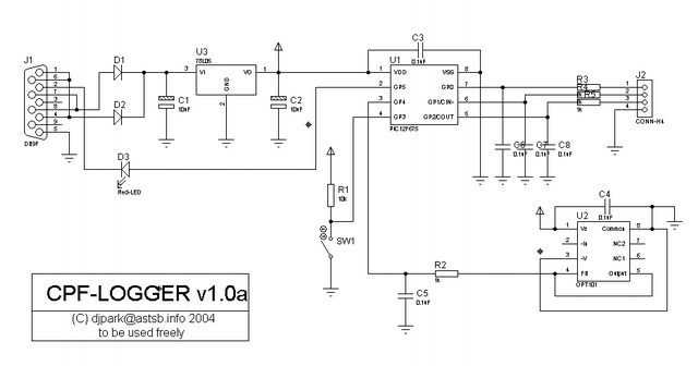
There is information not included in this main post. Read through the thread for more information on timer calibration and other useful information by cpfers. PEU pointed out that the TX should be connected to serial port pin 2...
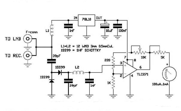
A circuit has been identified that integrates a voltage regulator and filter to isolate the voltage supplied by the receiver for powering an operational amplifier (op-amp) that drives a meter. Additionally, the circuit isolates the carrier frequency from the...
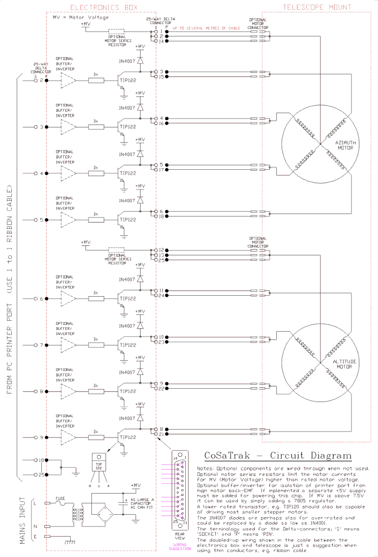
The back EMF voltage spikes produced by stepper motors, especially higher voltage motors, can damage a PC's printer port if connections are made incorrectly, flyback diodes are absent, or connected in reverse. The safest options are opto-isolated or buffered/inverted...
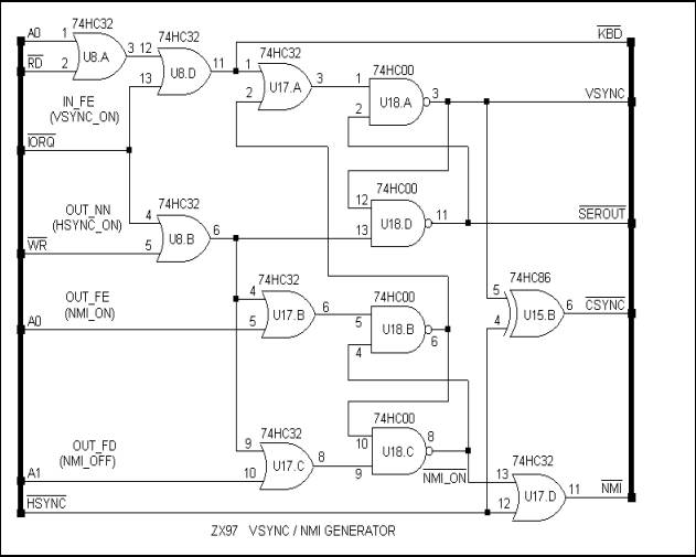
The ZX97 was developed as a discrete replica of the ZX81, which served as the first personal computer for millions. However, the ZX97 evolved into more than just a simple copy. While maintaining backward compatibility with the ZX81, it...
"Black Beauty" is a nickname for a classy Bakelite radio set. It features a dramatic, asymmetrical design with deep wraparound louvers and a bullet-like profile, exemplifying 1940s Streamline design. The radio is undergoing restoration of its electronics and cabinet....