
Solar Automation Switch Hardware
The circuit board serves as a versatile platform for home automation applications, allowing for modularity and customization. It is designed to integrate seamlessly into existing home environments, particularly with the Decora-style switch plates that are widely available. The use of microcontrollers from the PIC family ensures compatibility with a range of software applications, while the option to use different versions of the PIC microcontroller allows for scalability based on the complexity of the intended functions.
The CAN bus integration enables connectivity with other automation devices, facilitating a robust communication network within the home. The choice of a DC-DC converter ensures efficient power management, allowing the device to operate under various input voltage conditions. Additionally, the design includes provisions for expansion through daughter boards, which can be tailored to specific needs, thereby enhancing the overall functionality of the system.
The mechanical design considerations, including the use of acrylic for the switch plate and the provision for securing daughter boards, reflect a focus on durability and ease of installation. The visual indicators, such as the status LEDs, enhance user interaction by providing immediate feedback on the operational status of the device. Overall, this circuit board represents a comprehensive solution for modern home automation needs, balancing functionality, adaptability, and user-centric design.This is the main building block of the home automation system. My goal here was to design one circuit board that could be customized for different functions by selectively populating the board, adding daughter boards, and changing the software. Currently, this board is used to implement the functionality of a network connected light switch, a ther
mostat, interfacing a keypad to the CANOpen network, and implementing basic analog and digital I/O functionality. In terms of form factor, the board is a drop-in replacement for a decora style light switch, and can be used with any decora trim plate you pick at your favorite retail store.
The actual switch plate seen on the right is a 1/8" (3mm) thick piece of acrylic, which can be custom engraved if desired. Since it is translucent, you can see the status LED`s through the plate - and yes, pick any color you like.
The rest of this document describes the electrical and mechanical design of the board populated as a switch The schematic below shows the essential components of the circuit, the Thermostat specific components in the red box are not populated if you are building a switch: The CPU that is used for this module is either a PIC 18F248 or 18F258. While they are pin compatible, the latter has twice the amount of memory available, and is required if you want to implement more complex software.
The former is a little cheaper but will only allow you to implement the functionality of the basic switch described here. Currently, Microchip seems to be phasing out both of these chips and replacing them with the PIC 18F2480 and 18F2580.
While these are supposed to be compatible with the -248 and -258, I have not tried to recompile and run any of the software for these newer chips. The CAN bus connector is a MTA type polarized connector and carries the bus voltage of 24V DC as well as the two CAN bus signal lines.
The CAN bus lines are connected to the CAN driver chip, a MCP2551 or equivalent. R_MCP can be increased to 100k if the bus is operated at 125kBps and will reduce EMI by providing a slower slew rate of the CAN bus signals (see data sheet for details). The ICSP connector is a miniature type, but it has the same standard pinout as the 0. 1" version used by the Microchip ICD 2 programmer and clones. Thus, a short patch cable will allow you to program the PIC with any standard PIC programmer that supports ICSP.
The DC-DC step down power supply is more or less straight from the application note AN-1445 for the LM5009 demo board. The bus voltage of nominally 24 V is stepped down in the DC-DC converter (left bottom portion of the circuit) to +5V / 150mA which is sufficient to power the switch and any daughter boards.
As the LM5009 tolerates up to 95V input voltage, there is a lot of room for increasing the bus voltage if voltage drop becomes an issue. The connectors J1 and J2 allow the attachment of daughter boards to add further functionality. This is done by simply using a female 0. 1" pin headers on the switch board, and the male counter parts on the daughter boards. For added mechanical strength, the daughter boards can be secured with a pair of #4-40 screws and a spacer to the switch PCB.
See the respective web pages for the daughter boards for details. On the PCB side facing away from the wall when installed are LEDs, switches and their resistors. You will always want to populate the run and error LEDs and their resistors, as these provide visual information on the status of the node to the user. The remaining switches and LEDs are optional. In terms of functionality, each switch is doubled to provide mechanical support for the switch plate.
If you use this board for only a single switch, you can get away with a minimum of three switches (like left top and bottom / center right), four (two top/ two bottom) will provide the functionality of a double switch, and all six a triple switch. In this day and age of email spam, 🔗 External reference
Related Circuits
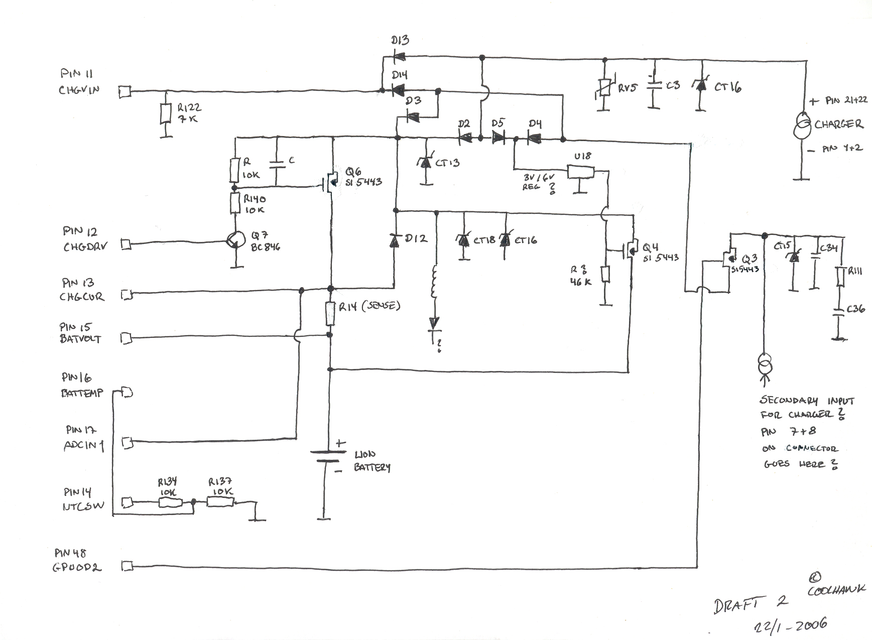
This is a basic hand-drawn schematic version 2. It will be transferred to Protel later when time permits. However, it provides a useful overview of the circuit, which can be charged from two different sources: USB or a standard...
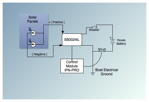
This is the fifth post in a five-part series on saving between $5,000 and $9,000 by installing a cockpit arch and a pair of solar panels on an Allied Princess ketch rigged sailboat named Aletheia. The series will continue...
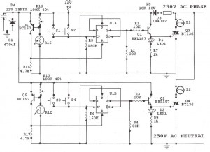
Light Sensitive Staircase Switch with Triac. The operation of the third circuit is quite similar, except that it incorporates photo sensitivity. The circuit is illustrated in the schematic. When there is insufficient light... The light-sensitive staircase switch circuit utilizes a...

If the total circuit resistance can be significantly reduced to less than 0.1 Ohm and a load of 0.4 Ohm or less is connected, over 1 kilowatt of free electrical energy can be obtained. There are two discrete voltage...
Operating high-beam headlights while driving on highways can significantly enhance visibility; however, it poses a blinding risk to other drivers. This straightforward circuit can be integrated into the headlight switch to facilitate automatic switching between high and low beam...
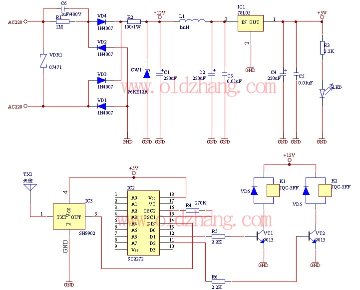
The production of this wireless remote control switch is relatively straightforward. All component parameters have been tested and verified. The installation of the reader component parameters can be completed during production, including the soldering of resistive and capacitive components...
Warning: include(partials/cookie-banner.php): Failed to open stream: Permission denied in /var/www/html/nextgr/view-circuit.php on line 713
Warning: include(): Failed opening 'partials/cookie-banner.php' for inclusion (include_path='.:/usr/share/php') in /var/www/html/nextgr/view-circuit.php on line 713