
Solar panel circuit

The schematic outlines the necessary components and their interconnections to achieve the desired functionality of illuminating an LED. The design typically includes a power source, such as a battery or DC power supply, which provides the necessary voltage and current. The LED requires a current-limiting resistor to prevent excessive current from damaging the diode.
In the schematic, the power source is connected to the anode of the LED through the resistor, while the cathode of the LED is connected to ground. This arrangement ensures that when the circuit is powered, current flows through the resistor and the LED, causing the LED to emit light.
Additional components may include a switch to control the circuit, allowing the user to turn the LED on and off. The PCB layout must consider the physical placement of components to minimize interference and optimize space. Proper routing of traces is essential to maintain signal integrity and prevent issues such as crosstalk or voltage drops.
The PCB design process also involves selecting appropriate materials, such as FR-4 for the substrate, and determining the thickness of the copper traces to ensure they can handle the required current without overheating. The final design can then be used to create a copper circuit board, which will be populated with the components and soldered to form a functional electronic device.A printed circuit board (PCB) and showed us a schematic of components that needed to be put onto the board in such a way so that an LED on the board would light up. The point of the PCB is so that you can plan for when you have a real copper circuit board that you are actually going to solder onto.
🔗 External reference
Related Circuits
P1 47K logarithmic potentiometer; P2, P3 47K linear potentiometers; R1, R3, R5 4.7K 1/4W resistors; R2 22K 1/4W resistor; R4 1M 1/4W resistor; R6 1.8K 1/4W resistor; R7 560Ω 1/4W resistor; C1, C4, C5, C7 10 µF 63V electrolytic...
This modified Hartley oscillator can be utilized to attract new friends or serve as a replacement doorbell. The modified Hartley oscillator is a type of electronic oscillator that generates a continuous waveform, typically a sine wave, using an LC (inductor-capacitor)...
This quartz crystal oscillator circuit exhibits greater stability compared to a parallel resonance circuit. It is capable of generating frequencies up to 30 MHz or even higher when utilizing BFR91 transistors for T1 and T2, along with reduced values...
This project is designed to program the 8-pin PIC12c508A and 18-pin PIC16F84 microcontroller chips to support the projects we have designed; however, it will also program a number of other 8-pin and 18-pin microcontrollers, and the full list can...

An audio test oscillator circuit typically produces a square wave if the oscillation frequency is low enough in relation to the amplifier's bandwidth. This circuit features a crystal-controlled oscillator designed for low-frequency sine wave generation, characterized by low distortion,...
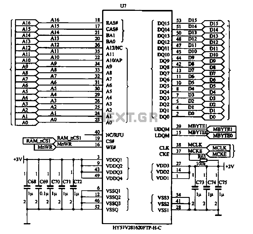
The Newman MP4 machine features three types of memory: data memory (U7), program memory (U8), and user memory (U9). Data memory is utilized for storing operational data, while program memory holds the machine's work program. User memory is designated...