
bright flash from flat battery diagram
The circuit functions by utilizing a basic LED driver configuration that incorporates a timing mechanism to create a flashing effect. The primary components of the circuit include a white LED, a resistor to limit current, and two electrolytic capacitors that store energy to be released in a burst, resulting in the bright flash.
When the supply voltage is applied, the capacitors charge up to the supply voltage, and once they reach a certain threshold, they discharge quickly through the LED. This rapid discharge creates a high-intensity flash of light. The selected resistor value is crucial as it determines the current flowing through the LED, ensuring it operates within its safe limits.
The use of two 100μF capacitors in parallel at 6V significantly improves the flash effect due to the increased charge storage capacity, allowing for a more substantial energy release. This design not only maximizes the brightness of the LED flash but also extends the operational lifespan of the circuit by allowing the use of lower-quality or older batteries, which may not provide optimal performance under continuous load conditions.
The circuit can be further enhanced by incorporating a timer IC or a microcontroller to control the flashing frequency, providing versatility for various applications such as emergency signaling, decorative lighting, or visual alerts. Proper heat dissipation measures should also be considered to ensure reliable operation over extended periods.This circuit will flash a white LED, on a supply from 2v to 6v and produce a very bright flash. The circuit takes about 2mA and old cells can be used. The two 100u electros in parallel produce a better flash when the supply is 6v. 🔗 External reference
Related Circuits
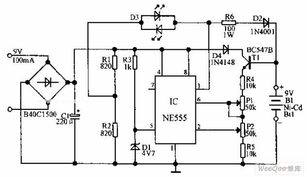
An automatic Ni-Cd battery charger circuit is depicted in the provided image. The internal comparator of the NE555 timer is configured to a reference voltage of 4.7V using a Zener diode. When the voltage at pin 6 exceeds this...
The article describes the process of building a charger controller board and programming the AVR microcontroller. A Li-Ion battery is needed for practice; the example battery mentioned has withstood considerable abuse. Knowledge of the battery's specifications, such as maximum...
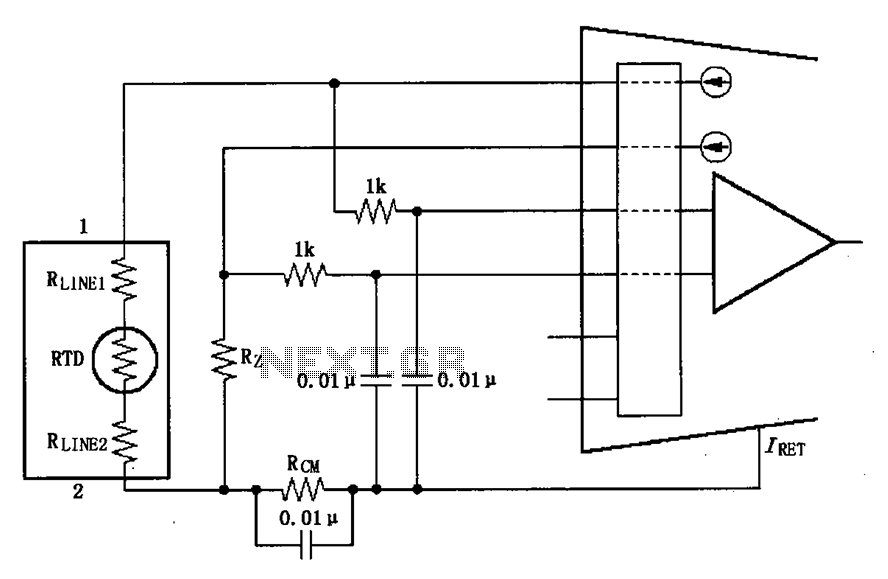
The long wire current loop transmission is susceptible to radio frequency (RF) interference, which can lead to errors in the sensitive input of the XTR108. This interference can occur particularly when the RTD sensor is located at a distance,...
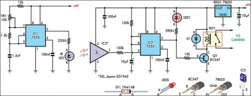
The IR detector (IC3) controls an LM 7555 CMOS timer (IC2) operating in monostable mode. When the beam is interrupted, IC2 is triggered, and its pin 3 output goes high for approximately half a second. This action extinguishes LED1...
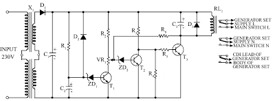
Due to the energy crisis, load shedding has become a common issue in several countries. Sudden power fluctuations, surges, and high voltage can damage sensitive household appliances such as TVs, VCRs, VCPs, and music systems. This circuit offers protection...

This jam circuit is designed for quiz contests, allowing participants to press their button (switch) to gain the first opportunity to answer a question. The circuit accommodates up to eight contestants, each assigned a unique number (1 to 8)....
Warning: include(partials/cookie-banner.php): Failed to open stream: Permission denied in /var/www/html/nextgr/view-circuit.php on line 713
Warning: include(): Failed opening 'partials/cookie-banner.php' for inclusion (include_path='.:/usr/share/php') in /var/www/html/nextgr/view-circuit.php on line 713