
solar charge
The described solar power system and battery charge controller is an innovative solution designed to optimize energy conversion and storage in small to medium-scale applications. It employs a sophisticated MPPT algorithm, allowing for efficient energy harvesting from the solar array by continuously adjusting the operating point to maximize power output. The use of a MOSFET in place of traditional diodes minimizes energy losses, enhancing overall efficiency and reducing thermal management requirements. This design is particularly advantageous for users seeking a reliable and efficient solar power solution without the complexities of microprocessor programming or advanced technical skills. The circuit's reliance on standard through-hole components increases accessibility for hobbyists and professionals alike, facilitating easier assembly and maintenance. The careful consideration of component selection and circuit topology ensures that the system can effectively manage varying load conditions and environmental factors, making it a robust choice for renewable energy applications.An unconventional, scalable high efficiency 12V solar power system and battery charge controller withlow voltage cutout to protect thebattery. (ideal for systems of 50W or less) This circuit was designed for small to medium lead acid systems and feature a lowish idle current ( 5mA ) which increases battery life on small capacity systems.
All the p arts in this design are through hole parts and can be found from a number of sources. None of the parts need programing and only a voltmeter and an adjustable supply is needed to calibrate the board. This makes it easy andcheap to build and maintain. Maximum power point tracking controllers are basically microprocessor controlled switch mode converters that vary the duty cycle up and down, hunting for the panel voltage that relates tothe maximum power output of the Photo Voltaic cells.
These converters currently provide the highestconversion efficiency. They dynamically adjust to allowfor changes in environmental conditions. An example would be if your battery is at 11V and the solar panel currently provides the optimum power at 15V, the MPPT would take in 15V at say 4A (60w) and provide the battery with 11V at 4, 9A (53. 9W) this includes a loss of 10% in the conversion. The same panel when connected directly may only put out 11V at 4, 2A (46. 2W). A microprocessor is inevitably needed and the circuit is generally more complex, this makes for a circuit that is less repairable and maintainable by its users that now require additional skills.
If you accept the additional complexity, or was never going to builds, repair or maintain your system yourself, the only reasonto choose or not to chooseMPPT is monetary cost. Assuming you are paying 3$ / Watt for yourpanel. If your MPPT converter is going to cost$35 more than a simple converter, theMPPT has to save you $35 or more in panel costs to make it the better option, that is to say35/3 =11, 7W.
Assuming the manufacturer`s claim of a 20% increase inperformance is accurate, MPPT converters are then more cost efficient at power levels over 11, 7W * 100 / 20 = 58. 8W. The most common solar charger consists of a Schottky diode to prevent the battery from draining into the PV panel and a shunt regulator that effectively short circuits the panel once the battery is fully charged.
One problem with this approach is diode losses and the resulting heat. If a 50W 12V panel supplies 4A to the battery, the Schottky diode will drop about 0, 4V across it dissipating about 1, 6W of heat. This requires a heat sink and loses power to heat. The problem is that there is no way of reducing the volt drop, paralleling diodes may share current, but the 0, 4V will still be there.
The circuit below uses a MOSFET in stead of the usual diode andthe primarypower loss is resistive. For comparison, a 40W PV system using the circuit below with IRFZ48 mosfets has a loss of about 1/4W on Q2. This means less heatand more power for your battery. More importantly though, MOSFETS have a positive temperature coefficient and can be paralleled to reduce the ON resistance.
Unlike the diode system, the totalpower loss can be reduced. There is nodiode between the solar panel and the load. This function is performed by Q2, a mosfet, used in reverse. The diode in the mosfet ensures that current will always flow from the PV panel to the load. If a significant voltage is present over Q2, Q3 turns on, charging C4, this allows U2c and U3b to turn mosfet Q2 on. Now the volt drop across the mosfet is determined by I*R, much lower than with a diode. C4 periodically discharges through R7, thenQ2 is turned off. If current was flowing from the Photo Voltaic panel, the self induced EMF acrossinductor L1 ensures that Q3 is turned on promptly.
This happens manytimes a second. In the case wherecurrent was flowing to the PV panel at the time Q2 turned off Q3 will not be turning on again andD2 limits L1`s self induced EMF. D2 may just be 🔗 External reference
Related Circuits
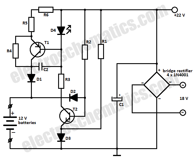
This battery charger circuit is designed to charge one or more batteries with a total nominal voltage of 12 V, which accommodates either ten NiCd batteries or six 2 V lead-acid batteries. The battery charger circuit operates by utilizing a...
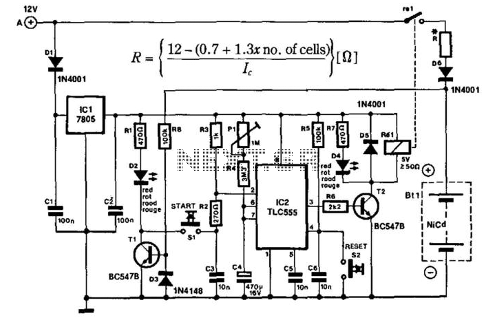
The portable charger is designed primarily for model enthusiasts to charge their NiCad batteries using a car battery outdoors. The circuit's supply voltage is regulated by IC1. When connected to the car battery, LED D2 illuminates only if the...
Here's a circuit diagram for Bob's "Vore-N-More" circuit containing the SmartCap solar engine: In this diagram, the "SmartCap" is just the 1.5 F storage capacitor, phototransistor, 2N3906 transistor, and 5.1K bias resistor. The idea is that after charging, a loss...
A 2 µF capacitor is charged to approximately 340 volts, and the discharge is controlled by a silicon-controlled rectifier (SCR). A Schmitt trigger oscillator (74C14) and a MOSFET (IRF510) are utilized to drive the low-voltage side of a small...
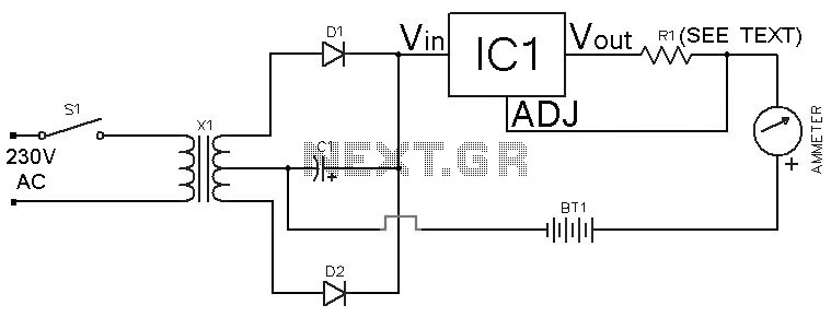
This Ni-Cd battery charger is a circuit utilizing the LM317 regulator IC. The design is straightforward and requires minimal components. By adjusting the value of resistor R1 between 1 ohm and 120 ohms, the charging current can be modified...
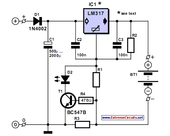
A simple NiCd charger can be constructed using readily available components and an economical LM317 or 78xx voltage regulator. The design incorporates a current limiter made up of resistor R3. The proposed NiCd charger circuit utilizes an LM317 or a...