
Solid State Relay
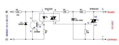
No description available.
Related Circuits
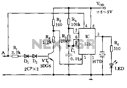
The circuit utilizes a 555 timer along with resistors R4, R5, and capacitor C1 configured in a controllable multivibrator mode. This setup forces the reset terminal (pin 4) to a specific state, allowing for control of the external logic...
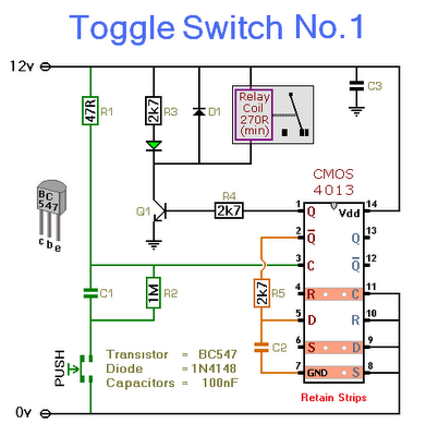
This circuit will activate and deactivate a relay with the press of a button. Any momentary push-to-make switch can be utilized. Pressing the button once will activate the relay, while pressing it a second time will deactivate the relay....
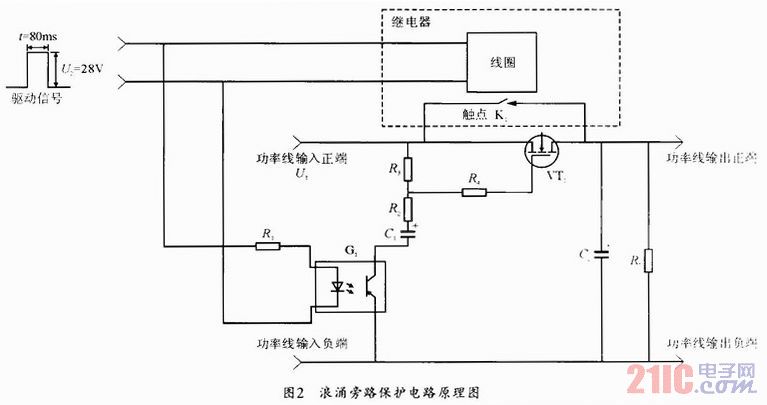
During the power-up of the apparatus, the capacitor is primarily responsible for the emergence of surge current. The schematic diagram of the principle is illustrated in Fig. 1. After K1 closes, the capacitor begins to charge, assuming that the...
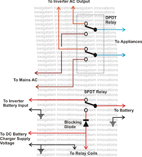
This inquiry has been presented multiple times on this blog regarding the implementation of a changeover selector switch for the automatic toggling of an inverter when AC mains power is available, and vice versa. The system must also enable...
This is a simple circuit which I built to one of my audio amplifier projects to control the speaker output relay. The purpose of this circuit is to control the relay which turns on the speaker output relay in...
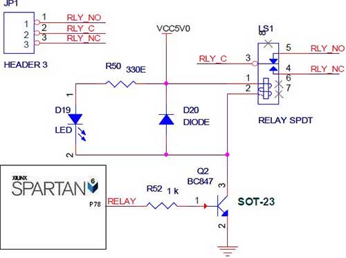
The Spartan-6 board features onboard 5V relay interfacing, as illustrated in the accompanying figure. The ULN2803 serves as a driver for the FPGA I/O lines, with the driver's outputs connected to the relay modules. A PTB connector is provided...