
bypass which improves the ability to resist surging of relay contact
The circuit involves a capacitor that plays a crucial role during the power-up phase, where it experiences a rapid increase in voltage, leading to a surge current. The surge current can be modeled using the relationship between capacitance, voltage, and resistance in the circuit. The initial surge is primarily influenced by the capacitor's ESR and ESL, which determine how quickly the capacitor can charge and how much current it can draw from the power supply.
As the relay coil is powered, it engages the mechanical components, allowing for the operation of the connected load. The timing of the relay activation is critical, as it must synchronize with the charging of the capacitor to prevent damage from excessive current. The circuit design includes protective features to manage the inrush current, ensuring that the components operate within safe limits. The use of appropriate resistors and capacitors in the charging circuit helps to control the rate at which the capacitor charges, thus managing the surge current effectively.
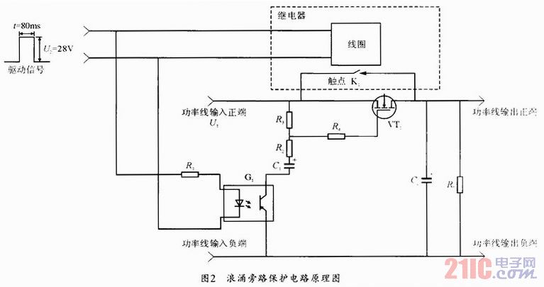
The design of the relay and its specifications, including the rated current and coil voltage, are selected to ensure compatibility with the overall circuit operation. The relay's quick response time is essential for applications requiring rapid switching, and the chosen model is suitable for handling the expected load. The circuit's performance can be verified through simulation or practical testing to ensure that it meets the design criteria and functions as intended during power-up scenarios.Generally, during power up of the apparatus, the capacitor is the main reason that surge current emerges, the synoptic diagram of the principle is shown in Fig. 1. Have it in the picture after K1 closes, the intersection of capacitor and C begin, charge, regard perfect condition direct current power supply can offer enough large electric current a
nd internal resistance for zero as direct current power supply, the intersection of switch and K1 and wire that connect, K1 contact resistance is zero, the wire thread is hindered as zero, At the time of condenser charge, the surge current produced can carry on approximate calculation according to formula 1. Though the electric capacity electric apparatus ESL has certain inhibit function on inputting the surge current, but inductance quantity is minor, inhibit function is minor, can neglect.
Usually the capacitor is ESR smaller, for example, measure under 100kHz, ESR of the liquid tantalum capacitor is generally several hundred milliohms, polyester capacitive ESR is generally dozens of milliohms, and the pottery capacitive FSR is generally several milliohms. So instant in the power up of capacitor, will produce the greater surge current. The above is the analysis that the surge current for the capacitor and produced at the time of power up carries on, if other apparatuses or components and parts have similar characteristics with the capacitor at the time of power up, will produce the greater surge current too, for instance, the storage battery will produce more than one hundred amperes of surge current under charging the form to read too.
After the driving signal is put through, the power up of coil, the sucking of electrical relay is combined into the mechanical movement course, dwell time 5- 15ms. Surging bypass protective circuit synchronizes with relay coil and receives the driving signal, before G1 was turned on, VT1 grid voltage input straight terminal voltage U1 with the line of power and is equal to, VT1 is the cutoff state.
After G1 turns on, the line of power inputs straight terminal voltage U1 charged for the electric capacity C1 by R2, R3, C1 is during the course of charging beginning, VT1 grid voltage calculated through formula 1, neglects the feed-through time of the light-coupled device, VT1 is a conducting state at this moment. Rise with C1 voltage constantly, VT1 grid voltage rises gradually, after C1 is charging and finishing, VT1 grid voltage inputs straight terminal voltage U1 with the line of power and is equal to, VT1 is the cutoff state, VT1 tube turns on time and depends on R2, R3 and C1 parameter and threshold voltage of VT1 tube grid, neglects the feed-through time usually less than 1 s of the photosensitive resister device, Turn on time and pass the formula 2 Calculate.
Usually, the driving signal of the electrical relay is a pulse signal, duration of high level t1 is 80ms, when the pulse signal is the high level, neglect the feed-through time of the light-coupled device, VT1 is a conducting state immediately; When the pulse signal is the low level, neglect the cut-off time of the light-coupled device, VT1 is a cutoff state immediately. 2If pass the formula 2 China calculates t and is smaller than high level duration of driving signal t1, then VT1 can be calculated through formula 2 while turning on time.
3If pass the formula 2 China calculates t and is greater than high level duration of driving signal t1, then it is equal to high level duration of driving signal t1 that VT1 turns on time. 3The electrical relay adopts the electrical relay of Model 3JB20-3, the rated current of single contact is 15A, the pick-up time of contact is 6.
4ms, the nominal voltage of the coil is 28V; 4Presume the line of power inputs straight terminal voltage U1 =28V, when not adopting the bypass protective circuit of surging, electric current waveform of adopting contact K1 of electric apparatus flows and has been sh 🔗 External reference
Related Circuits
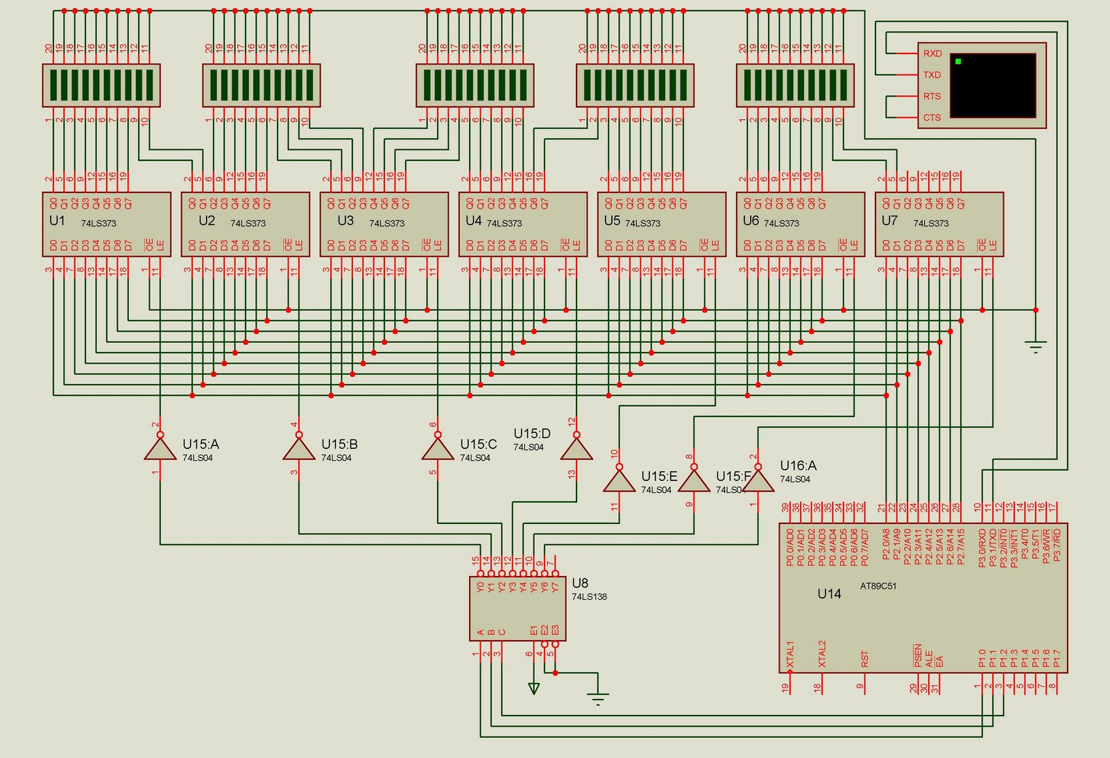
This project is designed to control up to 50 solid-state relays independently. It serves as an excellent learning resource for students who wish to expand the input-output lines of a microcontroller and control multiple devices. The ON or OFF...
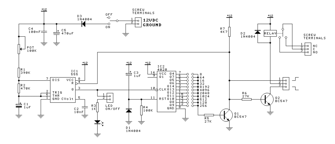
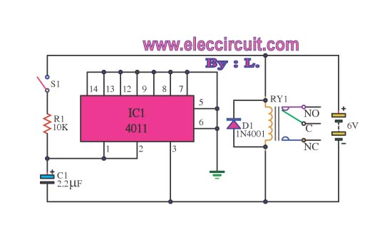
The 555 is configured in the standard astable oscillator circuit designed to give a square wave cycle at a period of around 1 cycle/sec. A potentiometer is included in the design so the period can be set to exactly...
Here are some circuit diagrams for driving relays from a microcontroller. Ensure the use of a 5-volt relay (this refers to the coil, not the load circuit) and verify that the relay has a sufficient rating for the load...
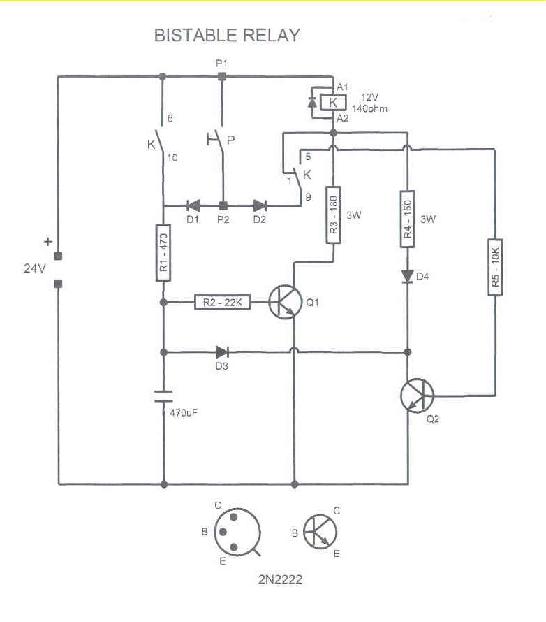
This circuit could be used to drive a monostable relay by a single momentary switch. Powered by 24 Volts, it works for a 12 Volts relay. When the button is pressed, Q1 is energized and the capacitor charges, while...
This circuit can be utilized to delay other appliances connected to the output of the relay. It operates to prevent equipment damage. This circuit is designed to provide a delay mechanism for appliances that are connected to a relay output....
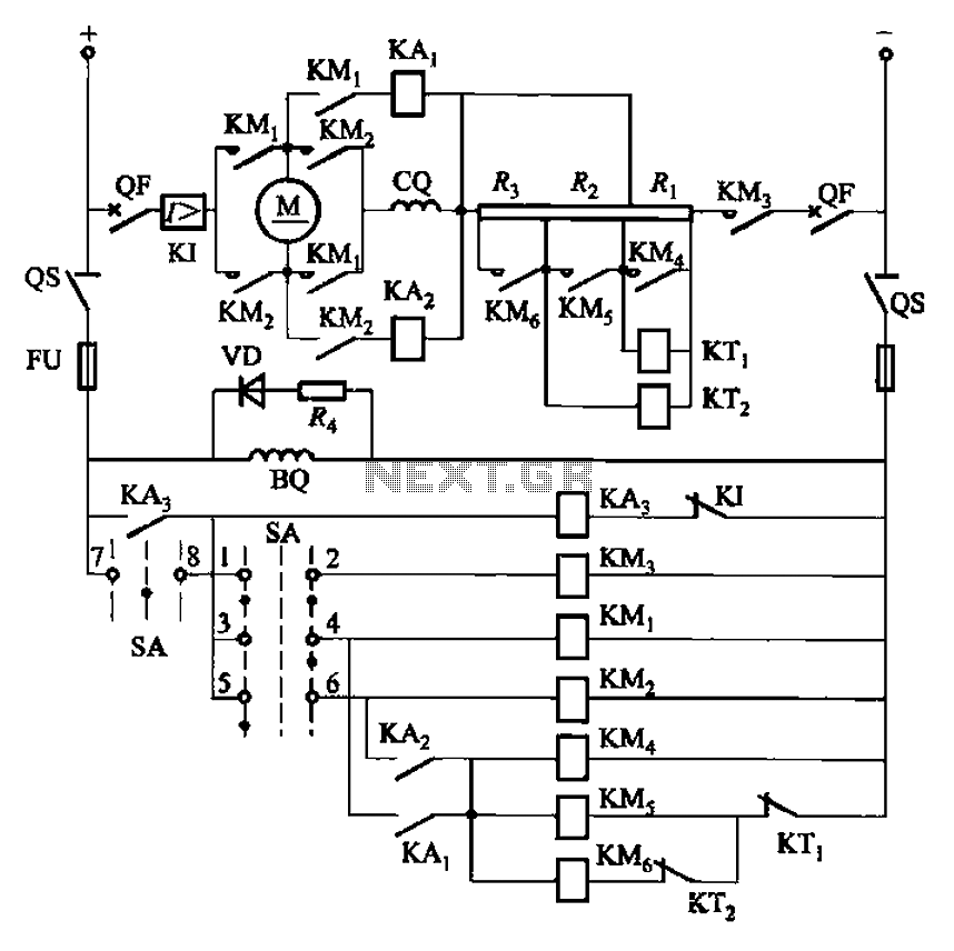
The circuit depicted in Figure 3-201 includes two starting resistors, with one controlled by a time relay. A master switch (SA) is utilized to manage the motor's reversing operation. The circuit incorporates a reverse braking mechanism, which is automatically...