
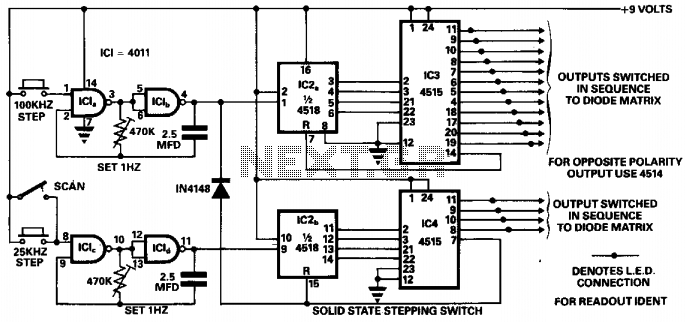
Solid state stepping switch
The circuit utilizes a microcontroller to manage the switching of channels and control the oscillators. The microcontroller is programmed to execute the single-stepping and scanning functions, ensuring that the transceiver can efficiently monitor channel occupancy without manual intervention. Each channel is connected to a digital output pin on the microcontroller, which activates the corresponding LED indicator when that channel is selected.
The scanning functionality is achieved through a timed loop within the microcontroller's firmware, allowing it to cycle through each channel at a set interval. This interval can be adjusted based on user requirements, providing a balance between speed and thoroughness in checking channel availability.
To accommodate the expansion to 256 channels, the circuit can be designed to include additional line encoders. These encoders convert the binary signals from the microcontroller into a format suitable for channel selection. The use of multiplexers may also be considered to manage multiple channel inputs, allowing for efficient switching without overloading the microcontroller's I/O capabilities.
Power supply considerations are crucial for mobile applications; thus, the circuit is designed to operate within a specified voltage range suitable for automotive environments. Protection features, such as fuses and voltage regulators, are recommended to safeguard the components from voltage spikes and fluctuations commonly encountered in mobile settings.
Overall, this circuit design provides a robust solution for managing multiple channels in a mobile transceiver application, ensuring both safety and functionality while enhancing user experience through intuitive LED indicators and expandable channel capabilities.This circuit was designed to make switching of a 48-channel mobile transceiver safe to operate while mobile. The oscillators allow for single-stepping or a scanning function. The scan facility allows for stepping through all 48 channels to check for occupancy or otherwise, and each output is indicated with an LED and labeled accordingly, so at-a-glance indication is possible.
With full scope of this circuit it is possible to scan 256 channels and by adding more 4 to 16 line encoders etc. you could switch to any required number. 🔗 External reference
Related Circuits
With the rapid development of the social economy, the demand for electric energy continues to increase. In light of the diminishing availability of non-renewable energy sources, such as fossil fuels, many countries are recognizing the importance of energy conservation...
The Motion Sensor Switch circuit is an automatic water sprinkler controlled by a motion sensor, with the option to incorporate an alarm or light function. Before starting the construction, it is advisable to contact a local electronics component vendor...
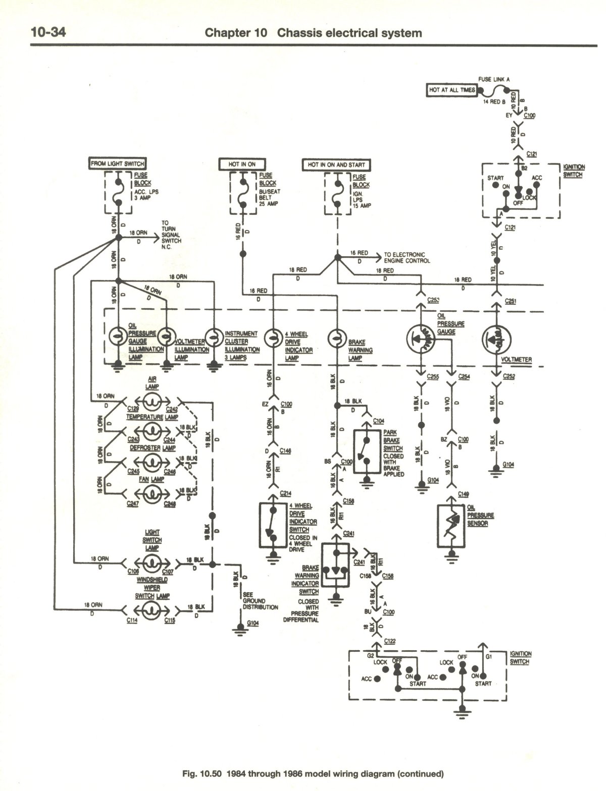
If there is no output at terminal 66 RED, it indicates a potential issue. The dash light dimmer may be set to the "OFF" position, or there could be significant corrosion on the wiper of the rheostat, preventing proper...
This is the primary component of the home automation system. The objective was to create a circuit board that can be customized for various functions by selectively populating the board, adding daughter boards, and modifying the software. Currently, this...
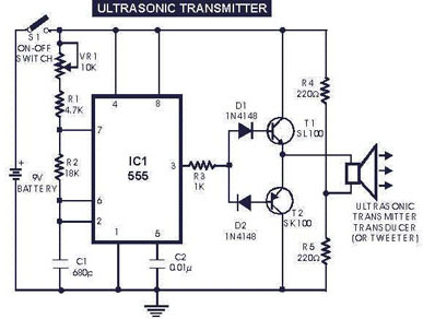
The circuit generates and transmits ultrasonic sound at frequencies between 40 and 50 kHz. It consists of a mini transmitter and a receiver circuit, where the transmitter produces ultrasonic sound, and the receiver detects this sound to activate a...
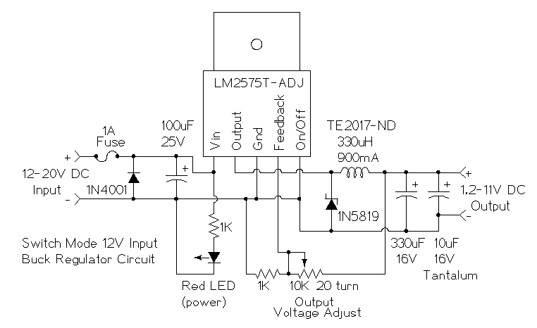
This is a simple buck mode switching regulator circuit diagram. This circuit is more efficient; switch mode regulators convert DC input voltage to pulses of high DC voltage. The DC pulses are used to charge a storage capacitor to...
Warning: include(partials/cookie-banner.php): Failed to open stream: Permission denied in /var/www/html/nextgr/view-circuit.php on line 713
Warning: include(): Failed opening 'partials/cookie-banner.php' for inclusion (include_path='.:/usr/share/php') in /var/www/html/nextgr/view-circuit.php on line 713